Beta 972/C10 Manuel utilisateur

972/C10

ASSORTIMENTO DI UTENSILI PER LA RIMOZIONE DI BULLONI DI FISSAGGIO
RUOTE DANNEGGIATI
ISTRUZIONI DI SICUREZZA AVVERTENZA
Assicurarsi che le norme sanitarie e di sicurezza nonché quelle stabilite dalle autorità
locali e quelle generali di buona pratica in officina vengano rispettate durante l’utilizzo
di utensili. NON utilizzare utensili danneggiati. Tenere gli utensili in buono stato e
puliti per un rendimento ottimale e all’insegna della massima sicurezza. Indossare
occhiali protettivi omologati. Indossare indumenti tali da evitare di rimanere impigliati
negli apparecchi. Tenere sotto controllo tutti gli utensili e i componenti in uso e non
lasciarli nel motore o in prossimità dello stesso.
iporre tutti i componenti nella cassetta e conservarla in un luogo sicuro, al riparo
dell’umidità e fuori dalla portata dei bambini.
Rif. Descrizione com onenti n. z
1 Portabussole a percussione 1
2 Bulino 1
3 Anello di protezione mano 1
4 Portalame 1
5 Inserti autoadattanti per bulloni antifurto 3
6 Lama A 1
7 Lama B 1
8 Bussola a macchina Ø 24 mm 1
IMPORTANTE
1) Non utilizzare le lame A(rif.6) e B(rif.7) quando si interviene su bulloni antifurto
temprati con impronte specifiche.
2) Se si interviene su bulloni antifurto temprati con impronte specifiche è necessario
utilizzare gli inserti monouso, in quanto si danneggerebbero le lame.
3) Per non rischiare di danneggiare il cerchio è consigliabile applicare del nastro
all’esterno del terminale del portalame.
O erazione di rimozione bullone mediante lame A e B
Per verificare la possibilità di utilizzo delle lame A e B testare la durezza del bullone
mediante il bulino presente nel kit. Se la punta segna la testa del bullone senza
presentare deformazioni o smussamenti è possibile utilizzare le lame, in caso
contrario no, in quanto si rovinerebbero senza ottenere risultati.
Esem io montaggio lama A
Fig. 1

Rimozione del terminale dal ortalame.
Selezionare la lama corretta in base alle dimensioni della testa del bullone da
rimuovere ed allo spazio presente tra bullone e cerchio.
Utilizzo lama A: è consigliabile utilizzarla quando la parte cilindrica removibile si
adatta allo spazio presente fra bullone e cerchio, in quanto ciò contribuirà a dare
stabilità durante l’utilizzo.
Nel caso la testa del dado sia di una dimensione tale da non permettere l’utilizzo
della lama A utilizzare la lama B.
Dopo aver disassemblato il portalame estraendo manualmente il terminale,
posizionare la lama selezionata come da esempi A è B e riassemblare il tutto.
Inserire l’anello di protezione mano sull’esagono da 24 mm del portalame.
Posizionare il portalame sulla testa del bullone, assicurarsi di essere posizionati in
asse, con le lame saldamente a contatto con lo stesso e con una mazzetta da circa
1,5 kg colpire ripetutamente (fig. 3) fino a quando la testa del bullone non presenterà
delle evidenti marcature lasciate dalle lame.
Fig. 3
A questo punto è possibile procedere alla rimozione del bullone mediante 3 differenti
utensili:
Portabussole a ercussione
Collegare Il portabussole a percussione con la bussola a macchina da 24 mm
presente nel kit, fatto ciò collegare il tutto al portalame, posizionare la protezione
mano sul portabussole, dopo aver posizionato la lama in corrispondenza dei segni
sul bullone inserirla nel portalame ed iniziare a colpire con una mazzetta da circa 1,5
kg fino allo svitamento del bullone. (Fig. 4)
Avvitatore a massa battente da ½ ollice
Collegare la bussola a macchina da 24 mm presente nel kit al portalame, assicurarsi
di essere posizionati in asse con il bullone e mediante l’uso di un avvitatore a massa
battente da ½ pollice procedere allo svitamento. (Fig. 5)
Esem io montaggio lama B
Fig. 2

Utensile manuale da ½ ollice
Collegare la bussola a macchina da 24 mm presente nel kit al portalame e mediante
l’utilizzo di un utensile manuale con attacco ½ pollice procedere allo svitamento(Fig.6)
Fig. 4 Fig. 5 Fig. 6
O erazione di rimozione bullone mediante inserti autoadattanti er bulloni
antifurto
Si utilizza questo genere di impronta monouso cod. 00972011 per la rimozione di
bulloni antifurto temprati. (Fig. 7)
Sui lati dell’inserto vi sono 2 differenti sezioni, le quali vanno scelte in base al
diametro dell’impronta posta sulla testa del bullone. Una volta identificato il lato
procedere Collegare Il portabussole a percussione con la bussola a macchina da 24
mm presente nel kit, fatto ciò collegare il tutto al portalame ed inserire lìinserto, fatto
ciò colpire con una mazzetta e procedere alla rimozione del bullone.
L’inserto è appositamente studiato per deformarsi e adattarsi all’impronta speciale dei
bulloni antifurto. (Fig. 8-9)
Fig. 7 Fig. 8 Fig. 9
N.B. Assicurarsi sempre che tutti gli utensili siano stati riposti nella cassetta e
conservare questa in un luogo sicuro al riparo dall’umidità.

REMOVAL TOOL ASSORTMENT FOR DAMAGED WHEEL FIXING BOLTS
SAFETY INSTRUCTIONS AND WARNING
Make sure that health and safety standards as well as the provisions established by
local authorities and general good practice standards applicable to garages are
complied with while using tools. DO NOT use any damaged tools. Keep your tools in
a good state of repair and clean for optimal performance and unparalleled safety.
Wear approved eye protection. Wear clothes that will not get caught in the tools.
Keep all the tools and parts being used under control and do not leave them in the
engine or near it.
eplace all the parts in the case and store it in a safe place away from humidity and
out of the reach of children.
Ref. Parts descri tion N°.of
cs
1 Impact socket holder 1
2 Centre punch 1
3 Hand protection ring 1
4 Blade holder 1
5 Self-adjusting bits for anti-theft bolts 3
6 Blade A 1
7 Blade B 1
8 Impact socket Ø 24 mm 1
IMPORTANT
1) Do not use blades A( ef.6) and B( ef.7) when working on hardened anti-theft
bolts with special heads.
2) When working on hardened anti-theft bolts with special heads, use disposable bits;
otherwise, the blades would get damaged.
3) In order not to risk damaging the rim, some tape should be applied outside the
blade holder terminal.
Bolt removal by means of blades A and B
In order to check whether blades A and B can be used, test the bolt for hardness by
means of the centre punch contained in the kit. If the tip marks the bolt head without
showing any deformation or chamfering, the blades can be used; otherwise, they
cannot be used, as they would get damaged without producing any results.
Blade A installation exam le
Fig. 1

Removing terminal from blade holder.
Select the correct blade according to the dimensions of the head of the bolt to be
removed and the amount of space available between the bolt and the rim.
Using blade A: it should be used when the removable cylindrical part fits between the
bolt and the rim, as this will help provide stability while using it.
If the nut head is so sized as to prevent blade A from being used, use blade B.
After disassembling the blade holder by pulling out the terminal by hand, place the
selected blade as per examples A and B, and reassemble the blade holder.
Fit the hand protection ring onto the 24-mm hexagon of the blade holder.
Place the blade holder on the bolt head; check for alignment with the bolt, making
sure that the blades are firmly in contact with the bolt; use a 1.5 kg club hammer to
repeatedly hit the bolt head (Fig. 3), until this shows some clear marks as left by the
blades.
Fig. 3
The bolt can then be removed by means of 3 different tools:
Im act socket holder
Connect the impact socket holder to the 24-mm impact socket driver contained in the
kit; then connect it all to the blade holder; place the hand protection ring on the
socket holder, after placing the blade in such a way as to match the marks on the
bolt; fit it into the blade holder and start hitting by means of a club hammer weighing
approximately 1.5 kg to unscrew the bolt. (Fig. 4)
½" im act wrench
Connect the 24-mm impact socket driver contained in the kit to the blade holder;
check for alignment with the bolt and unscrew it by means of a ½" impact wrench
(Fig. 5).
½" hand tool
Connect the 24-mm impact socket driver contained in the kit to the blade holder and
unscrew the bolt by means of a ½" hand tool. (Fig. 6)
Blade B installation exam le
Fig. 2

Fig. 4 Fig. 5 Fig. 6
Bolt removal by means of self-adjusting bits for anti-theft bolts
This kind of disposable impression is used cod. 00972011 for removing hardened
anti-theft bolts. (Fig. 7)
The sides of the bit have 2 different sections, which should be chosen according to
the diameter of the bolt head. After identifying the side, connect the impact socket
holder to the 24-mm impact socket driver contained in the kit; then connect it all to the
blade holder and fit in the bit; finally, hit with a club hammer and remove the bolt.
The bit has been specially designed to get deformed and adjust to the special heads
of anti-theft bolts. (Fig. 8-9)
Fig. 7 Fig. 8 Fig. 9
NB: Always check that all the tools have been replaced in the case and store it in a
safe place away from humidity.

ASSORTIMENT D’OUTILS POUR EXTRAIRE LES BOULONS ENDOMMAGÉS DE
FIXATION DES ROUES
INSTRUCTIONS DE SÉCURITÉ ET AVERTISSEMENT
S’assurer que les règles de santé et de sécurité, ainsi que les règles établies par les
autorités locales et les règles générales de bonnes pratiques dans les ateliers soient
respectées lors de l'utilisation des outils. NE PAS utiliser d’outils endommagés.
Maintenir les outils en bon état et propres pour un rendement optimal et la plus
grande sécurité. Porter des lunettes de protection homologuées. Porter des
vêtements adhérents pour éviter qu'ils ne se prennent dans les appareils. Surveiller
tous les outils et les composants utilisés, ne pas les laisser dans le moteur ou à
proximité. anger tous les composants dans la caisse à outils et la garder dans un
lieu sûr, à l’abri de l’humidité et hors de portée des enfants.
IMPORTANT
1) Ne pas utiliser les lames A( èf.6) et B( èf.7) en cas d'intervention sur les boulons
antivol en acier trempé avec empreintes spécifiques.
2) En cas d'intervention sur les boulons antivol en acier trempé avec empreintes
spécifiques, il est nécessaire d’utiliser les embouts à usage unique, car les lames
pourraient s’endommager.
3) Pour ne pas risquer d’endommager le cercle, il est recommandé d’appliquer du
ruban à l’extérieur de l’embout du porte-lame.
O ération d’extraction du boulon à l’aide des lames A et B.
Pour vérifier la possibilité d’utilisation des lames A et B, tester la dureté du boulon au
moyen du pointeau présent dans le kit. Si la pointe marque la tête du boulon sans
présenter de déformations ou ébavurages, il est possible d’utiliser les lames,
autrement, ils s’abîmeront sans obtenir de résultats.
Réf. Descripon des composants Nbe de ces
1 Porte-douilles à frapper 1
2 Pointeau 1
3 Bague de protection 1
4 Blade holder 1
5Embouts auto-ajustables pour
boulons antivol 3
6 Lame A 1
7 Lame B 1
8 Douille à chocs Ø 24 mm 1

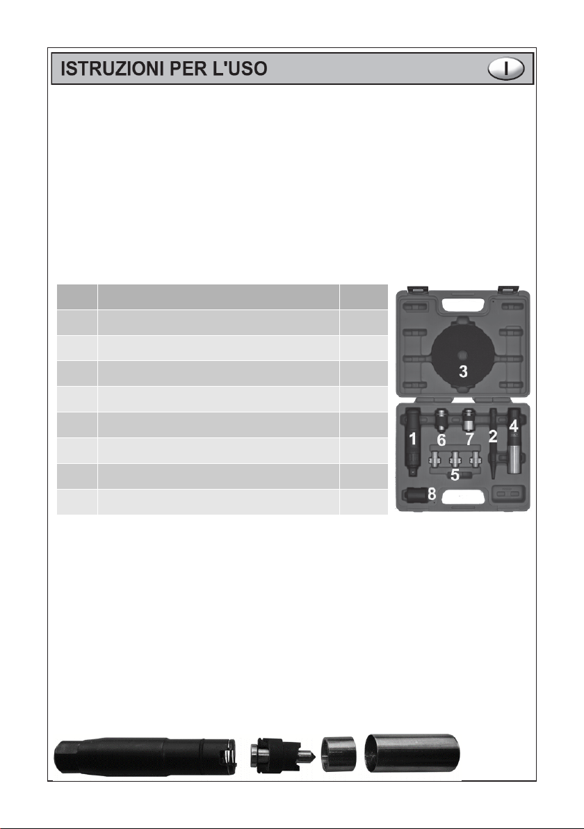
Extraction de l’embout orte-lames
Sélectionner la lame correcte en fonction des dimensions de la tête du boulon à
extraire et à l'espace entre le boulon et le cercle.
Utilisation de la lame A : à utiliser lorsque la partie cylindrique amovible s'adapte à
l'espace présent entre le boulon et le cercle, car cela apportera de la stabilité
pendant l'utilisation. Si la dimension de la tête de l'écrou ne permet pas l'utilisation de
la lame A, utiliser la lame B.
Après avoir désassemblé le porte-lame en retirant l'embout à la main, placer la lame
sélectionnée conformément aux exemples A et B et réassembler le tout.
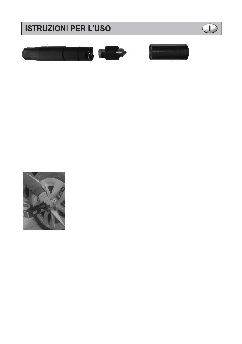
Introduire la bague de protection des mains sur l'hexagone de 24 mm du porte-lame.
Placer le porte-lame sur la tête du boulon, s'assurer d'être positionnés dans l'axe,
avec les lames solidement en contact avec le boulon et, à l'aide d'une massette
d'environ 1,5 kg, frapper à plusieurs reprises (fig. 3) jusqu'à ce que la tête du boulon
ne présente des traces évidentes laissées par les lames.
Fig. 3
À ce stade, il est possible de procéder à l'extraction du boulon à l'aide de 3 outils
différents:
Porte-douilles à fra er
Brancher le porte-douilles à frapper à la douille à chocs de 24 mm présente dans le
kit, après quoi relier le tout au porte-lames, positionner la protection des mains sur le
porte-douilles, après avoir placé la lame à hauteur des signes sur le boulon,
l'introduire dans le porte-lames et procéder à l'aide d'une massette d'environ 1,5 kg
jusqu'au dévissage du boulon (Fig. 4).
Clé à chocs extracteur à inertie de ½ ouce
elier la douille à chocs de 24 mm présente dans le kit au porte-lames, s'assurer de
se trouver dans l'axe du boulon et à l'aide d'une clé à chocs à frapper de ½ pouce,
procéder au dévissage (Fig. 5).
Exem le de montage lame B
Fig. 2
Exem le de montage lame A
Fig. 1

Outil manuel de ½ ouce
elier la douille à chocs de 24 mm présente dans le kit au porte-lames et à l'aide d'un
outil manuel avec raccord ½ pouce, procéder au dévissage (Fig. 6).
Fig. 4 Fig. 5 Fig. 6
O ération d'extraction du boulon à l'aide des embouts auto-ajustables our
boulons antivol.
Ce type d'empreinte jetable est utilisé à la morue. 00972011 pour retirer les boulons
antivol durcis. (Fig. 7)
Sur les côtés de l'embout se trouvent 2 sections différentes qui sont choisies en
fonction du diamètre de l’empreinte située sur la tête du boulon. Après avoir choisi le
côté, procéder au branchement du porte-douilles à frapper à la douille à chocs 24 mm
présente dans le kit. Après quoi, relier le tout au porte-lames et introduire l'embout,
puis frapper avec une massette et procéder à l'extraction du boulon.
L’embout est expressément étudié pour se déformer et s'adapter à l'empreinte
spéciale des boulons antivol (Fig. 8-9).
Fig. 7 Fig. 8 Fig. 9
N.B. S'assurer systématiquement que tous les outils aient été rangés dans la caisse à
outils qui devra être à son tour rangée dans un lieu sûr, à l'abri de l'humidité.
Table des matières
Langues :
Autres manuels Beta Outils électriques

Beta
Beta 1471M/C22 Supplément

Beta
Beta 666N Manuel utilisateur

Beta
Beta 1934BV Supplément

Beta
Beta 678/55 Manuel utilisateur

Beta
Beta 1550U Manuel utilisateur

Beta
Beta 599 DGT/6 Manuel utilisateur

Beta
Beta 1569/F Manuel utilisateur

Beta
Beta 1827F Manuel utilisateur

Beta
Beta 960KC-M8/M9/M10 Manuel utilisateur

Beta
Beta 1924XM Supplément

Beta
Beta 666 Manuel utilisateur

Beta
Beta 599DGT-A/10 Manuel utilisateur

Beta
Beta 1827 Manuel utilisateur

Beta
Beta 1984 20V/1200BMC Supplément

Beta
Beta 1808 Manuel utilisateur

Beta
Beta 1921N3 Supplément

Beta
Beta 3027/10 Manuel utilisateur

Beta
Beta 1951A Supplément

Beta
Beta 1947M Supplément

Beta
Beta 1550U Manuel utilisateur


