Bestop PowerBoard 75152-15 Manuel utilisateur
Installation Instructions
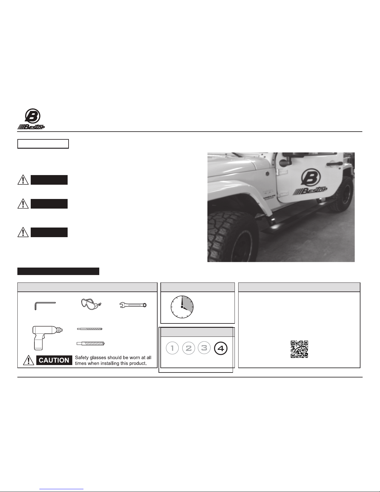
PowerBoard®
Automatic Retracting Running Board
Vehicle Application:
Jeep Wrangler Unlimited
2007- 2016
Part Number 75152-15
Installation Instructions - PowerBoard®© 2016 Bestop, Inc.P1 - 75152 Rev. C 0416
WARNING
Read and follow, precisely, all installation instructions provided when
installing this product. Failure to do so may result in a poor t, and could
place occupants of the vehicle in a potentially dangerous situation.
WARNING
WARNING
The manufacturer strongly recommends that this product be
professionally installed.
Failure to carefully follow the electrical installation steps
could result in severe electrical shock which could harm the installer and/or damage
the vehicle.
This product is designed primarily to enhance the appearance
and comfort of the vehicle. Do not rely in any way on the components of this product
to protect the occupants within the vehicle, or to protect against injury or death in
the event of an accident. Never operate the vehicle in excess of manufacturer’s
specications.
Installation Tips
WEAR SEAT BELTS AT ALL TIMES
SupportInstallation TimeTools
Skill Level
4 Hours
4 - Difficult
We’re here to help!
Gto to http://www.Bestop.com
and click “Ask a Question”
Safety Glasses
1/8” Drill
3/8” Drill
5mm Allen Wrench 10mm Wrench
Drill- Driver
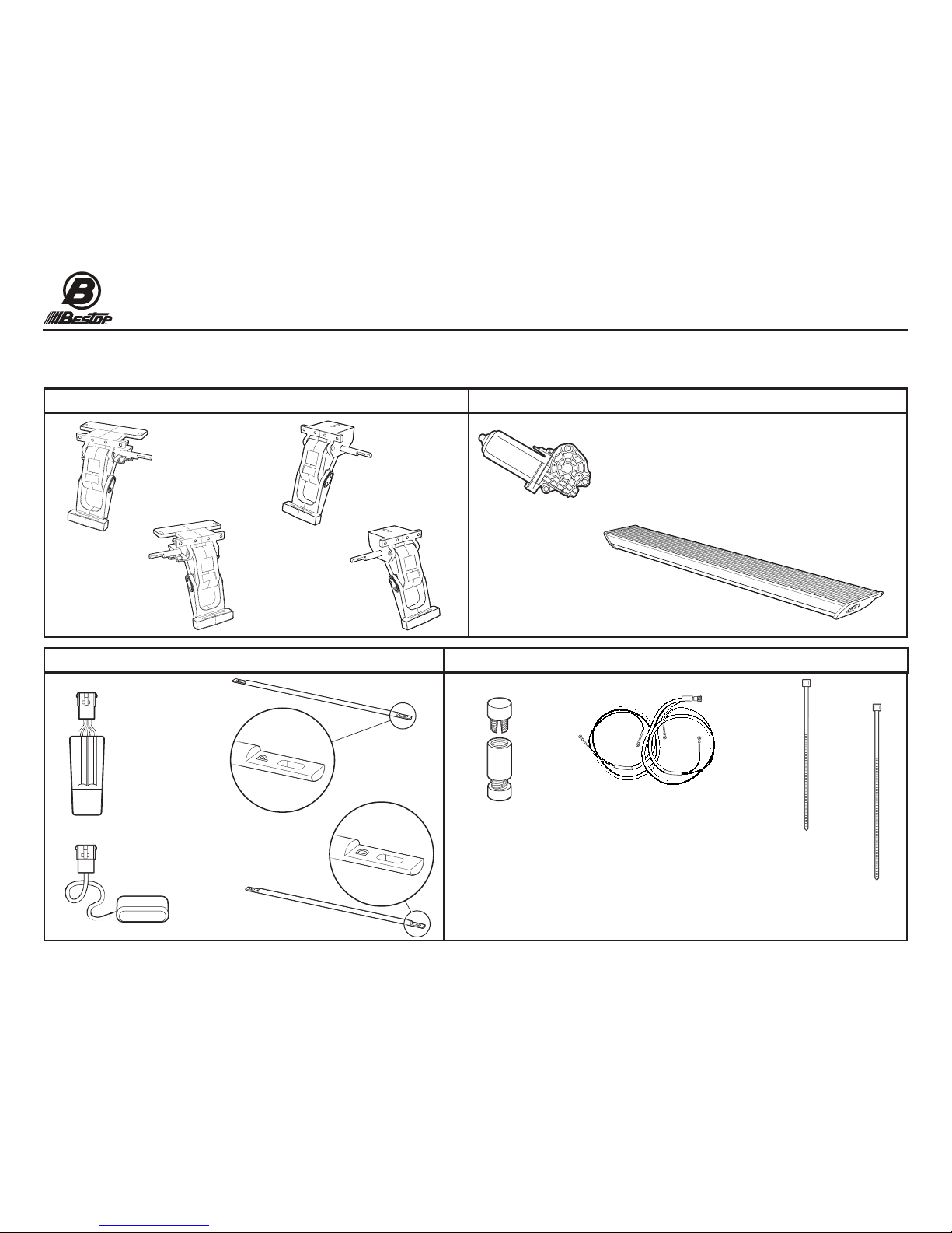
Parts List
- Required parts for installation
Installation Instructions
PowerBoard®
Automatic Retracting Running Board
Vehicle Application:
Jeep Wrangler Unlimited
2007- 2016
Part Number 75152-15
P2 - 75152 Rev. C 0416 Installation Instructions - PowerBoard®© 2016 Bestop, Inc.
Idler Linkage - Right
Part #517.90
Qty. 1
Idler Linkage - Left
Part #517.91
Qty. 1
Running Board Assembly
Part #517.92
Qty. 2
Motor
Part #496.12
Qty. 2
Controller
Part #496.11
Qty. 1
Light
Part #470.15
Qty. 4
11” Cable Tie
Part #470.02
Qty. 2
7” Cable Tie
Part #460.99
Qty. 25
Torsion Bar
Right- Passenger
Part # 525.21
Qty.1
Torsion Bar
Left- Driver
Part # 525.22
Qty.1
Motor and Idler Linkages
Span Bars, Controller, Receiver, Lights
Motor and Running Board
Wiring Harness & Sensors, Cable Ties
Motor Linkage - Left
Part #525.19
Qty. 1
Motor Linkage - Right
Part #525.20
Qty. 1
Posi-Tap®
Part # 470.03
Qty. 4
Wiring Harness
Part #474.73
Qty. 1
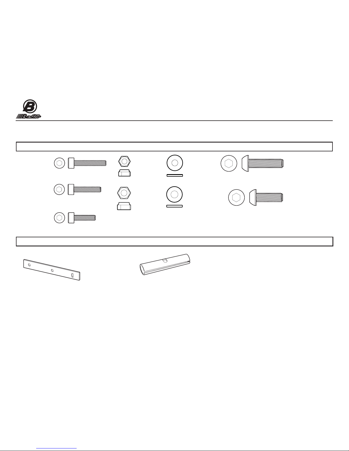
Parts List
- Required parts for installation
Installation Instructions
PowerBoard®
Automatic Retracting Running Board
Vehicle Application:
Jeep Wrangler Unlimited
2007- 2016
Part Number 75152-15
P3 - 75152 Rev. C 0416 Installation Instructions - PowerBoard®© 2016 Bestop, Inc.
#M6-1.0 x 35
Socket Cap Screw
Part # 460.95
Qty. 6
#M8-1.25 x 25
Button Head Screw
Part # 522.95
Qty. 4
#M6 Flat Washer
Part # 481.96
Qty. 14
#M6-1.0 x 20
Socket Cap Screw
Part # 470.00
Qty. 8
#M8-1.25 x 20
Button Head Screw
Part # 473.83
Qty. 8
Fasteners
Miscellaneous Hardware
Drill Template
Part # 523.18
Qty. 1
Torsion Bar Collar
Part # 517.95
Qty. 4
#M6-1.0 x 30
Socket Cap Screw
Part # 523.15
Qty. 4
#M8-1.25
Hex Nut
Part #473.84
Qty.1
#M8 Flat Washer
Part #470.05
Qty.12
#M6 -1.0
Nylon Lock Nut
Part #490.93
Qty.4

P4 - 75152 Rev. C 0416 Installation Instructions - PowerBoard®© 2016 Bestop, Inc.
Page 4
WARNING
PowerBoard®Fastener Tightening Sequence
Fasteners Must Be Tightened in This Sequence to Promote Smooth Operation
1. Mount linkages to the body of the Jeep nger tight only. (see sections 6 through 8).
2. Install and tighten the torsion bars to specication. (see section 8)
3. Loosely install boards to mounting foot of linkages. (see section 9)
4. Retract the board, then tighten the board to the MOTOR LINKAGE ONLY. (Rear)
5. Open the vehicle door to extend the board, then close the vehicle door to retract
the board. Tighten the board to the FRONT idler linkage when the board
is retracted or in the up position. (See section 10)
6. Now tighten linkages to the Jeep body and Welded Body Flange.
Torque all fasteners to the following specications:
5-7 ft-lbs (6.79-9.40 NM / 60-84 in-lbs)
Do not exceed 7 ft-lbs.
Section 1 Important Fastener Tightening Information
P5 - 75152 Rev. C 0416 Installation Instructions - PowerBoard®© 2016 Bestop, Inc.
Page 5
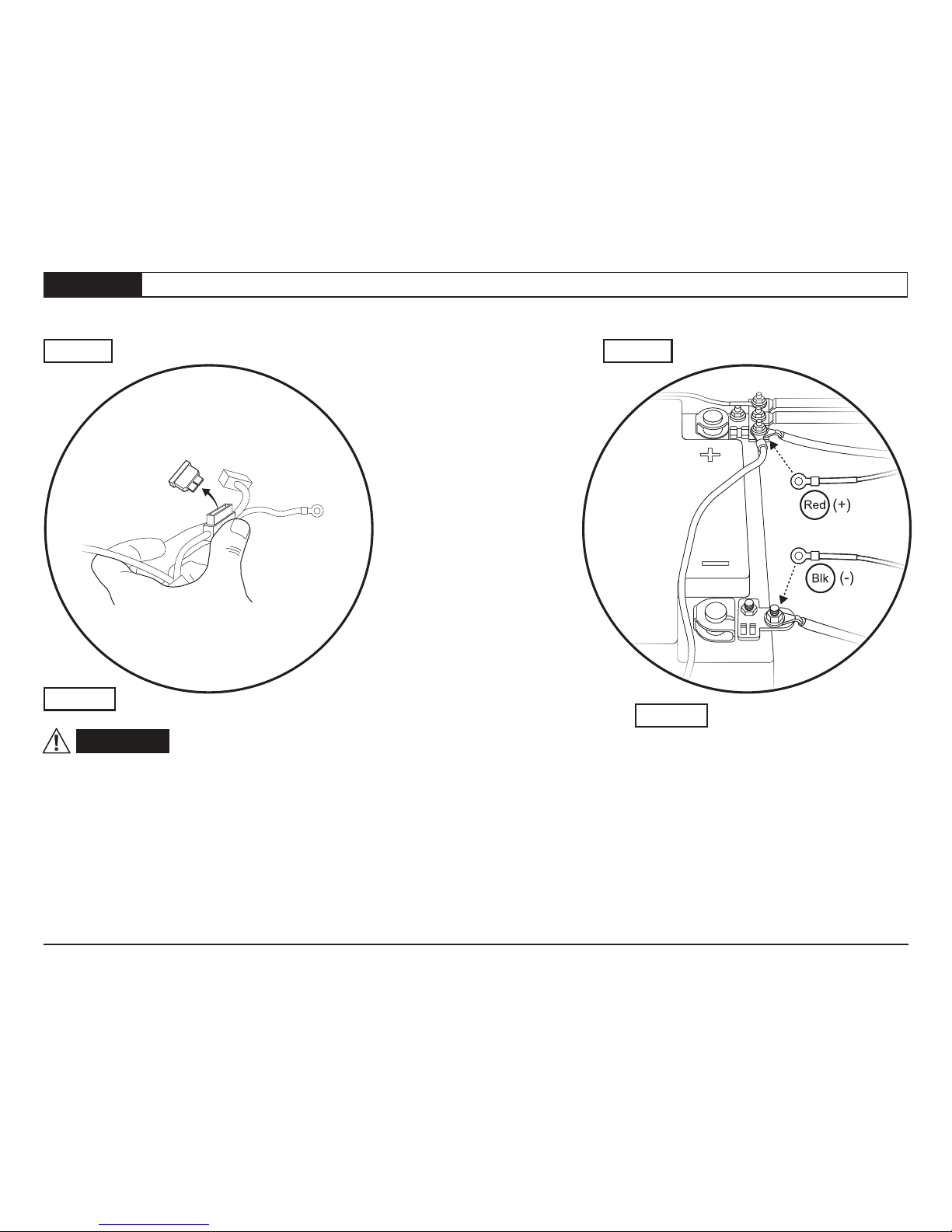
Step 1 Step 2
Remove the fuse from the wiring harness.
Failure to do so could result in severe
electrical shock which could harm the
installer and/or damage the vehicle.
Step 1
Step 2
Connect the red lead from the wiring
harness to the battery positive and the
black lead to the battery negative.
WARNING
Red (+)
Blk (-)
Ground
Fuse
Section 2 Remove Fuse and Attach Wiring Harness to Battery
P6 - 75152 Rev. C 0416 Installation Instructions - PowerBoard®© 2016 Bestop, Inc.
Page 6
Route the short leg of the Wiring Harness
(labeled “Side 1”) down the firewall and
along the frame rail of the vehicle, on the
same side as the battery. Keep the harness
away from heat and exhaust system. Secure
the harness to the frame using the #460.99
7” cable ties.
Route the long leg of the Wiring Harness
(labeled “Side 2”) across the firewall and
down the opposite side of the vehicle from
the battery location. Secure the harness to
the firewall and frame using the #460.99
7” cable ties.
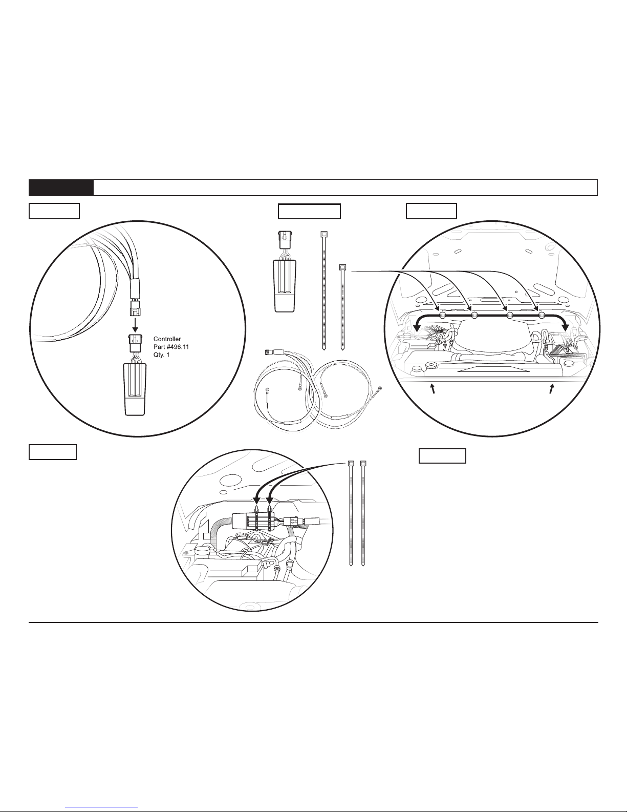
Step 2
Connect the Wiring Harness to the
Controller. Make sure that the locating
tabs are fully engaged.
Secure the Controller to the vehicle
wiring harness with two 11” Cable
Ties.
Step 1 11”
Side 1
Short Leg
Wiring
Harness Side 2
Long Leg
7” Cable ties
as needed
along firewall
Controller
Part #496.11
Qty. 1
Wiring Harness
Part # 523.19
Qty. 1
Hardware
11” Cable Tie
Part #470.02
Qty. 2
7” Cable Tie
Part #460.99
Qty. 25
Controller
Part #496.11
Qty. 1
Wiring Harness
Part # 523.19
Qty. 1
Step 1 Step 2
Section 3 Install Controller & Wiring Harness
P7 - 75152 Rev. C 0416 Installation Instructions - PowerBoard®© 2016 Bestop, Inc.
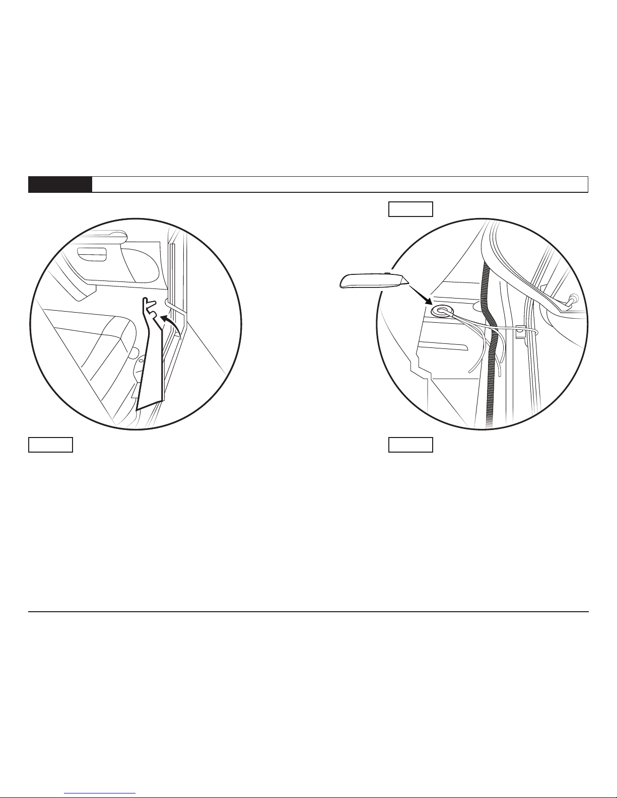
Page 7Section 4 Remove Door Sills & Route Trigger Wires
Step 1
Step
Step
2
2
Utility Knife
Remove the front door sills on both driver and pas-
senger sides of the vehicle.
Passenger side shown.
Lift up the carpet.
Slit the rubber grommet in the oor.
Thread the trigger wires through the grommet and
into the passenger compartment.
P8 - 75152 Rev. C 0416 Installation Instructions - PowerBoard®© 2016 Bestop, Inc.
Page 8
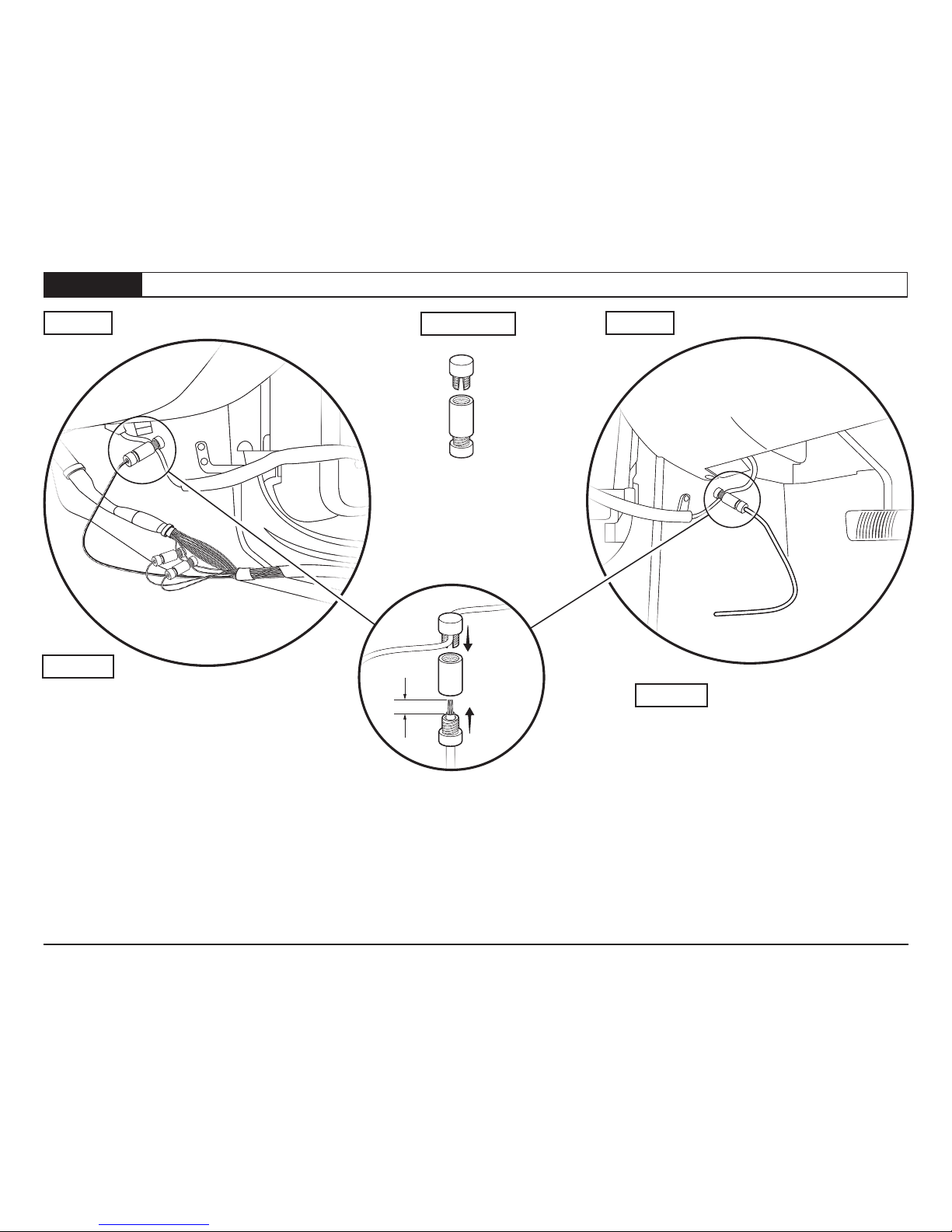
Hardware
Step 2
Step 1
Section 5 Connect Trigger Wires
Step 2
Posi-Tap®
Part # 470.03
Qty. 1 per door
Step 1
3/8”
Passenger Side - Use the Posi-Taps®to connect
the trigger wires to the matching wires in the
factory loom.
- Violet / White wire in loom coming from the
front door
- Violet /Yellow and Violet /Grey in main loom
in the door sill
NOTE: Occasionally the actual wire color may be
different than the one stated here, or there may
be more than one wire with the same color.
You will need to install the motor and test each
wire until you nd the wire that functions properly.
Driver Side - Route the trigger wire under the
carpet to the door sill. Use a PosiTap®to
connect to the violet wire coming from the door.
NOTE: Occasionally the actual wire color may be
different than the one stated here, or there may
be more than one wire with the same color.
You will need to install the motor and test each
wire until you nd the wire that functions properly.
P9 - 75152 Rev. C 0416 Installation Instructions - PowerBoard®© 2016 Bestop, Inc.
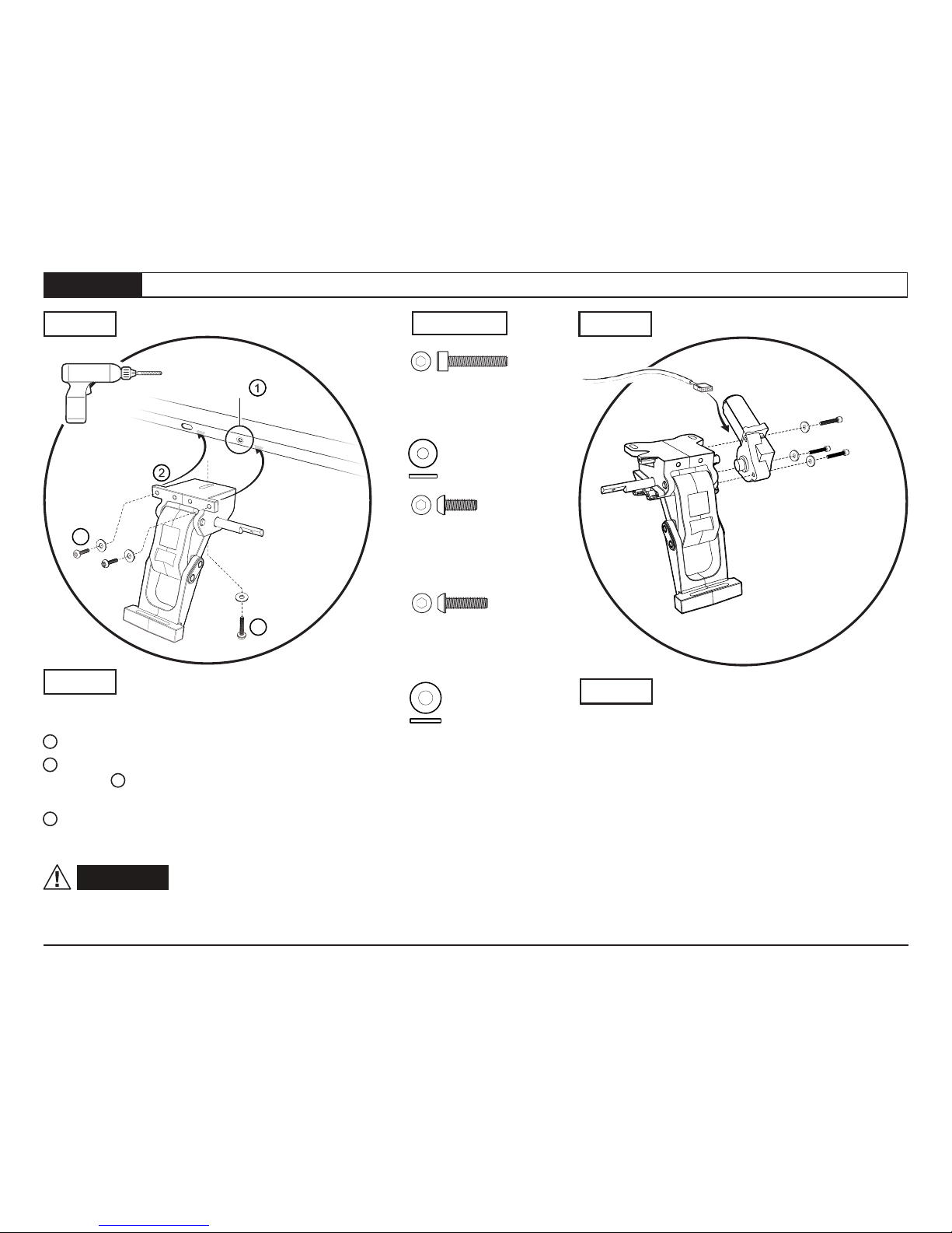
Page 9Section 5 Install Idler Linkages and Linkage Motors
Hardware
#M6-1.0 x 35
Socket Cap Screws
Part # 460.95
Qty. 3 per linkage
#M6 Flat Washer
Part # 481.96
Qty. 3 per linkage
#M8-1.25 x 20
Button Head Screw
Part # 473.83
Qty. 2 per Linkage
#M8-1.25 x 25
Button Head Screw
Part # 522.95
Qty. 1 per Linkage
Step 2
2
1
Enlarge this hole
in the welded
body flange to
3/8” diameter
3
4
Step 1 Step 2
Attach a Motor to each Motor Linkage using three
#M6-1.0x35 Socket Cap Screws, with three #M6
Flat Washers.
Left (Driver) side motor linkage shown above.
Repeat for Right (Passenger) side of the vehicle.
With the Motor-Linkage assembly near the vehicle
mounting position - underneath the rear of the
vehicle door opening - attach the wiring harness
motor connector to the motor.
Repeat on the Right (Passenger) side of the vehicle.
Step 1 Step 2
Motor Linkage - Left
Driver Side
Part #517.89
Qty. 1
Motor
Part #496.12
Wiring harness
motor connector
The Idler Linkage mounts toward the front of the
vehicle. Left (driver) side shown.
1 Enlarge the small hole as shown to 3/8” dia.
2 Mount the Idler Linkage behind the welded body
ange using 3 two #M8-1.25x25 Button Head
Screws with #M8 Flat Washers.
4 Install one #M8-1.25x25 Button Head Screw
with #M8 Flat Washer through the bottom of the
Idler Linkage into the bottom of the vehicle body.
WARNING Only tighten the screws
holding the Idler Linkages to the vehicle nger tight
at this time.
Motor Linkage - Left
Driver Side
Part #525.19
Qty. 1
#M8 Flat Washer
Part #470.05
Qty. 3 per Linkage
Using the #M8-1.25 x 20mm Button Head
Screw and the #M8-1.25 Hex Nut,
attach the supplied drilling template
#523.18 to the body ange, centering the
slotted template hole over the pre-existing
slotted hole in the welded body ange,
toward the rear fender.
Mark the position of the middle hole in the
template on the welded body ange.
Driver side shown.
1 Drill a 1/8” hole in the welded body ange,
using the middle hole of the drilling template.
2 Remove the template, and drill out the
1/8” hole to 3/8”.
Driver side shown. Repeat this process on the
passenger side of the vehicle.
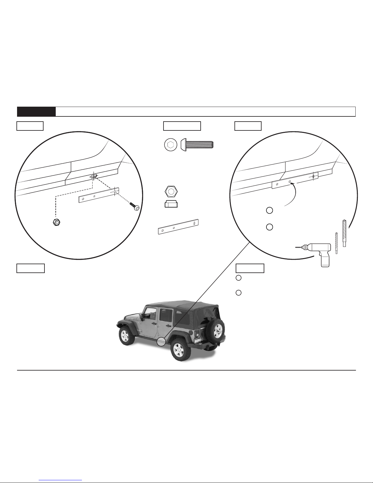
P10 - 75152 Rev. C 0416 Installation Instructions - PowerBoard®© 2016 Bestop, Inc.
Page 10Section 7 Drill Holes for Motor Linkage Mounting
Step 2
Step 1
Step 1 Hardware Step 2
2
1
1/8” Drill
3/8” Drill
Drill a 1/8” hole
using the template
Remove the template
and drill out the 1/8”
hole to 3/8”
Drill Template
Part #523.18
Qty.1
#M8-1.25
Hex Nut
Part #473.84
Qty.1
#M8-1.25x20
Button Head Screw
Part #473.83
Qty.1
Table des matières
Autres manuels Bestop Autre


