BENEKOV S16 Manuel utilisateur

BOILER OPERATING AND INSTALLATION
INSTRUCTION MANUAL
BENEKOV S16
BENEKOV S26
BENEKOV S51

2
Dear client,
Thank you for purchasing a BENEKOV S series automatic wood pellet boiler and
placing your confidence in our company, BENEKOVterm s.r.o. of Horní Benešov.
To use your new product correctly, from the outset, please first read this operating
manual, especially Chapters 7 and 8. Please follow the information below and
observe the manufacturer’s instructions or those of the service company that
installed your boiler.
These boilers were approved for operation in EU member states by Strojírenský
zkušební ústav, s.p. (Engineering Testing Institute, state-owned-enterprise), Notified
Body 1015, Authorized Body 202, Brno based on certificate no. B-30-00612-16 of
31.5.2016.
In accordance with Government Regulation No. 176/2008 Coll., Annex 1, section
1.7.4. it is an
ORIGINAL INSTRUCTION MANUAL
Copyright 2011 Leopold Benda jr. et al., license BENEKOVterm spol. s.r.o.
All rights reserved.
All texts, images are subject to copyright and other intellectual property protection.

3
Table of Contents
1. Boiler use and advantages..................................................................................................................4
2. Technical specifications......................................................................................................................4
3. Specified fuel for boilers .....................................................................................................................6
4. Boiler description................................................................................................................................6
4.1. Boiler design....................................................................................................................................6
4.2. Control and safety elements of the boiler......................................................................................18
4.3. Boiler accessories..........................................................................................................................18
5. Boiler placement and installation......................................................................................................22
5.1. Regulations and directives ............................................................................................................22
5.2. Boiler placement options ...............................................................................................................23
6. Commissioning of the boiler - instructions for contracted service organizations .............................25
6.1. Electric connection using via connectors.......................................................................................25
6.2. Verification activities before start-up..............................................................................................29
6.3. Putting into operation.....................................................................................................................29
7. Boiler operation by user....................................................................................................................31
7.1. Making fire in the boiler .................................................................................................................31
7.2. Boiler operation..............................................................................................................................32
7.3. Boiler shutdown.............................................................................................................................32
7.4. Residual risks and their prevention ...............................................................................................33
8. Boiler maintenance...........................................................................................................................34
9. Troubleshooting................................................................................................................................35
10. Guidelines for sustained compliance with the environmental parameters of the product...............36
11. Instructions for product disposal after the end of its service life......................................................37
12. Guarantee and liability for defects...................................................................................................37
4
1. Boiler use and advantages
Boiler use:
The BENEKOV S16 hot water boiler is designed for heating small, low-energy family houses, cottages and
other building facilities whose heat output demand does not exceed 20 kW.
The BENEKOV S26 hot water boiler is designed for heating family houses, cottages, office buildings, small
establishments and building facilities whose heat output demand does not exceed 26 kW.
The BENEKOV S51 hot water boiler is designed for heating medium-sized buildings - shops, schools,
recreational facilities, large family houses, office buildings, establishments and other building facilities, whose
heat output demand does not exceed 49 kW.
Boiler advantages:
•Automatic boiler operation
•Possibility of combustion of a renewable energy source in the form of wood pellets
•Mechanical fuel supply from standardized container (or general bunker) into the combustion chamber
•Possibility of increasing the capacity of the basic standardized fuel container with additional modules
•Automatic cleaning of heat transfer surfaces of the heat exchanger
•Simple, quick operation and maintenance
•Low operating costs
•3-draught design of the exchanger guaranteeing high efficiency
•Low emissions for the neighbourhood
•Controlled combustion assisted by lambda probe
•Modulation of thermal output over the entire power output range
•Possibility of connecting boiler auto ignition (optional)
•Possibility to connect ash removing device (optional)
•Modern design
2. Technical specifications
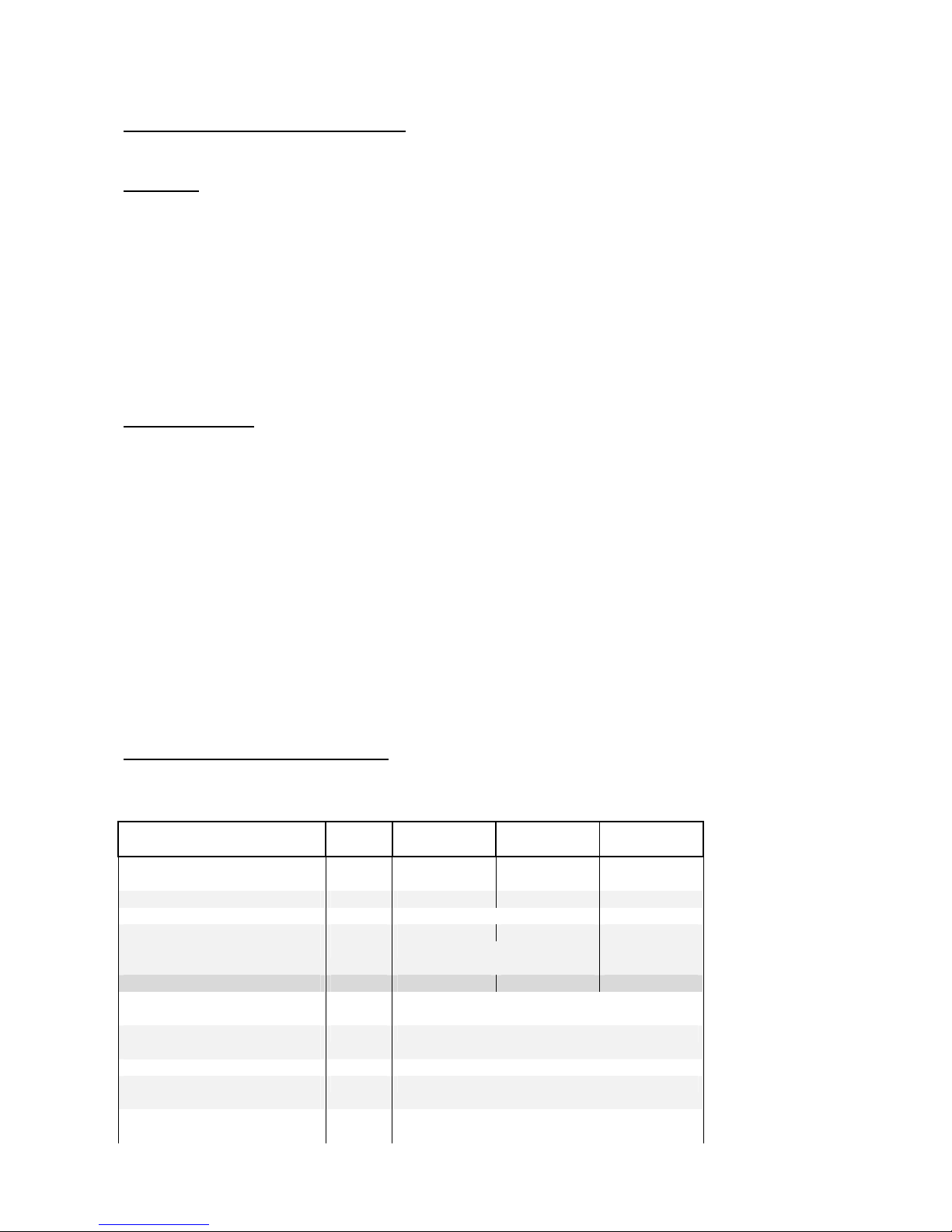
Tab. no. 1 Dimensions and technical parameters of boilers
Boiler type BENEKOV
S16 BENEKOV
S26 BENEKOV
S51
Weight (boiler body + feeder
to the boiler + turnstile) Kg 340 410 765
Water compartment volume dm
3
62 89 175
Flue gas duct diameter Mm 145 195
Boiler heat transfer surface m
2
1,90 2,84 5,64
Boiler dimensions: Mm Fig. no. 5, 6, 7 Fig. no. 8, 9,
10
Boiler class according to ČSN
EN 303-5 5
Maximum permissible
operating pressure Bar 2,0
Testing pressure Bar 4,0
Recommended operating
temperature of heating water °C 65 - 80
Lowest temperature of the
inlet water °C 60
5
Hydraulic loss
∆T = 10 K
mbar
4
16
8
∆T = 20 K mbar 1,6 4 2
Sound pressure level Lp
A
dB < 65dB (A)
Required chimney draft mbar 0,12 – 0,15 0,15 – 0,20 0,20 – 0,25
Boiler connections - heating
water Js G 1” G 6/4”
- return water Js G 1” G 6/4”
Supply voltage 400V / 16A / ~ 50 Hz
Electrical power input at rated
power output W 33 38 51
Electrical power input at
minimum power output W 15 15 23
Electrical power input in
STAND BY mode W 6 6 6
Electrical protection IP 20
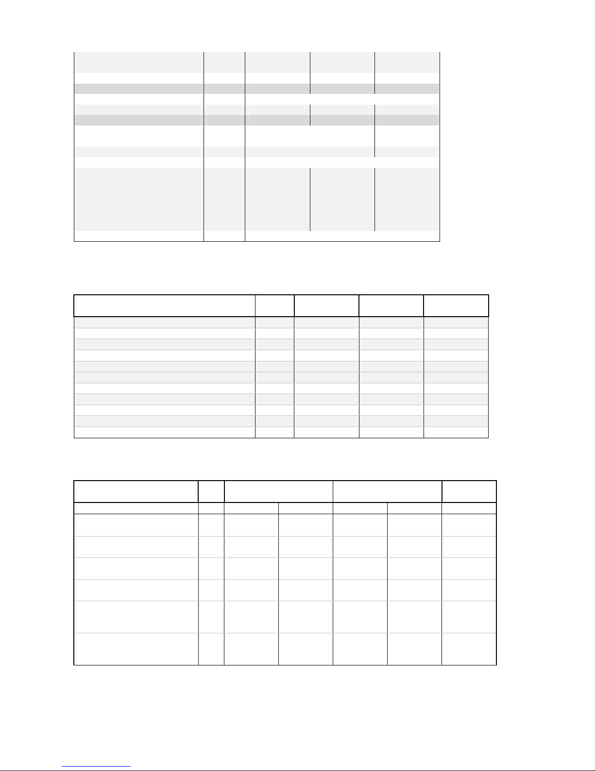
Tab. no. 2 Thermal technical parameters of BENEKOV S boiler series with the combustion of wood
pellets
Boiler type BENEKOV
S16 BENEKOV
S26 BENEKOV
S51
Nominal output kW 20 26 49
Adjustable power output kW 6,0 – 20 7,7 – 26 14,6 – 49
Fuel consumption kg . h
-1
1,3 – 4,3 1,8 – 5,7 3,1 – 10,5
Output in attenuation kW 1,7 1,7 1,7
Fuel consumption in attenuation kg . h
-1
0,4 0,4 0,4
Flue gas temperature: - at rated output °C 108 109 95
- at minimum output °C 73 69 61
Efficiency % 92,1 90,8 90,7
Mass flow rate of flue gas at the output
- at rated output kg . s
-1
0,008 0,016 0,024
- at minimum output kg . s
-1
0,004 0,006 0,011
Tab. no. 3 Parameters of standardized fuel storage containers to the boilers of BENEKOV S series
Boiler type BENEKOV S16 BENEKOV S26
BENEKOV
S51
Silo diameter mm 1 200 2 000 1 200 2 000 2 500
Dimension of the filling
opening in the fuel container mm octagon
φ1200 octagon
φ2000 octagon
φ1200 octagon
φ2000 octagon
φ2500
Weight of the basic fuel
container module kg 121 286 121 286 397
Weight of the additional fuel
container module kg 30 48 30 48 60
Capacity of the basic fuel
container module dm
3
740 2700 740 2700 4000
Capacity of 1 pc of the
additional fuel container
module
dm
3
500 1300 500 1300 2000
Firing time at rated output
with full basic container
module
h 143 523 80 293 236

6
3. Specified fuel for boilers
The fuels specified in tab.no.4 are prescribed (under guarantee) fuel types for BENEKOV series boilers.
Tab. no. 4 Prescribed fuel
Type of fuel
according to ČSN EN
303-5
Average
[mm]
Length
[mm]
Bulk
density
[kg/m
3
]
Water
content
[%]
Ash
content
[%]
Calorific
capacity
[MJ.kg
-1
]
C1 - wood pellets
φ6 - 14
max. 30
600 - 650 max. 12
max. 1,5
min. 17
ATTENTION! Poor quality fuel can significantly affect performance and emission parameters of
the boiler.
The pellets must comply with the requirements of the standard ČSN EN 14961-2.
4. Boiler description
The design of BENEKOV S boilers meets the requirements of:
ČSN EN 303-5: 2013 - Heating boilers - Part 5: Heating boilers for solid fuels, hand and automatically
stocked, nominal heat output of up to 500 kW - Terminology, requirements,
testing and marking.
4.1. Boiler design
The main part of the boiler, based on a fuel understoking design, is the boiler body that is welded from
steel boiler plates. All parts of the boiler body at the interface of flue gases and heating water are
made of sheet metal with a thickness of 5 mm. In front of the boiler body there is a combustion
chamber with a burner; at the back of the boiler body there is a 3-draft multi-plate heat exchanger
providing the decisive transfer of heat from flue gases to the boiler water. The finned heat exchanger
is fitted with an automatic cleaner, which during operation of the boiler continuously cleans the heat
exchange surfaces.
The burner, based on a fuel understoking design, consists of a screw fuel feeder and a steel grate.
The fuel feeder consists of a trough for fuel supply, a channel for supplying combustion air and a
flexible interconnection that serves for pressure equalization under the fireplace and which prevents
smoke penetration into the fuel tank during the combustion process. The burner is fitted with a ceramic
reflector that directs the exhaust gas flow, reduces fly dust and thus facilitates complete combustion.
Under the combustion chamber there is an ash drawer and shaped bed for the eventual installation of
an ash remover.
Beside the boiler there is a screw feeder that transports fuel from the external container to the burner.
The feeder consists of two screw conveyors (feeding from the bunker + feeding into the boiler) with a
turnstile between them. This serves to create an air gap between the two screw conveyors and avoids
any ignition of fuel in the container. In addition, the cover of the feeder from the bunker that transports
fuel above the turnstile is fitted with an emergency fire extinguishing system.
Depending on the position of the fuel feed screw towards the boiler drum, the boiler is manufactured in
two versions:
•Right version - the fuel feeder is on the right of the boiler body when viewed from the front
•Left version - the fuel feeder is on the left of the boiler body when viewed from the front
Furthermore, according to the design of your boiler room, you can select three mounting positions for
feeding from the bunker to the boiler. A side design (see fig. No. 5 and 8), front design (see fig. No. 6
and 9) and rear design (see Fig. 7 and 10).

7
The combustion air fan/s is/are placed on the side of the boiler by the fuel container. The boiler’s
control unit regulates the amount of combustion air.
The inlet and outlet of heating water for connection to the heating system is located in the rear part of
the boiler. BENEKOV S16 and S26 have two outlets with internal thread G 1", BENEKOV S51 has two
outlets with internal thread G 6/4". The outlet with G 1/2" thread in the bottom part on the right is used
to install the drain cock. At the rear of the boiler on the top, there is a flue gas exhaust adapter leading
to the chimney.
The flue gas exhaust increases the chimney draft and is an integral part of the equipment of S series
boilers.
The boiler body, its lid and doors are insulated with non-toxic insulation that reduces losses by
dissipating heat to the surroundings.
The steel casing is provided with a quality powder paint colour finish.
8
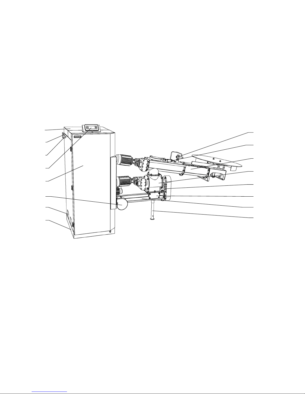
Fig. no. 1 Front view of the BENEKOV S16 and S26 boiler
1. Boiler lid
2. Locking bolt of firing flap
3. Firing flap lever
4. Boiler control unit display
5. Door cover
6. Combustion air fan
7. Preparation for ash remover
8. Boiler body feet cover
9. Emergency fire extinguishing system
10. Cover limit switch of the bunker feeder
11. Feeding from the bunker
12. Turnstile
13. Turnstile chain
14. Overflow cleaning cap
15. Feeding to the boiler
16. Feeder foot
1
16
15
14
12
13
11
10
9
2
3
4
5
6
7
8
9
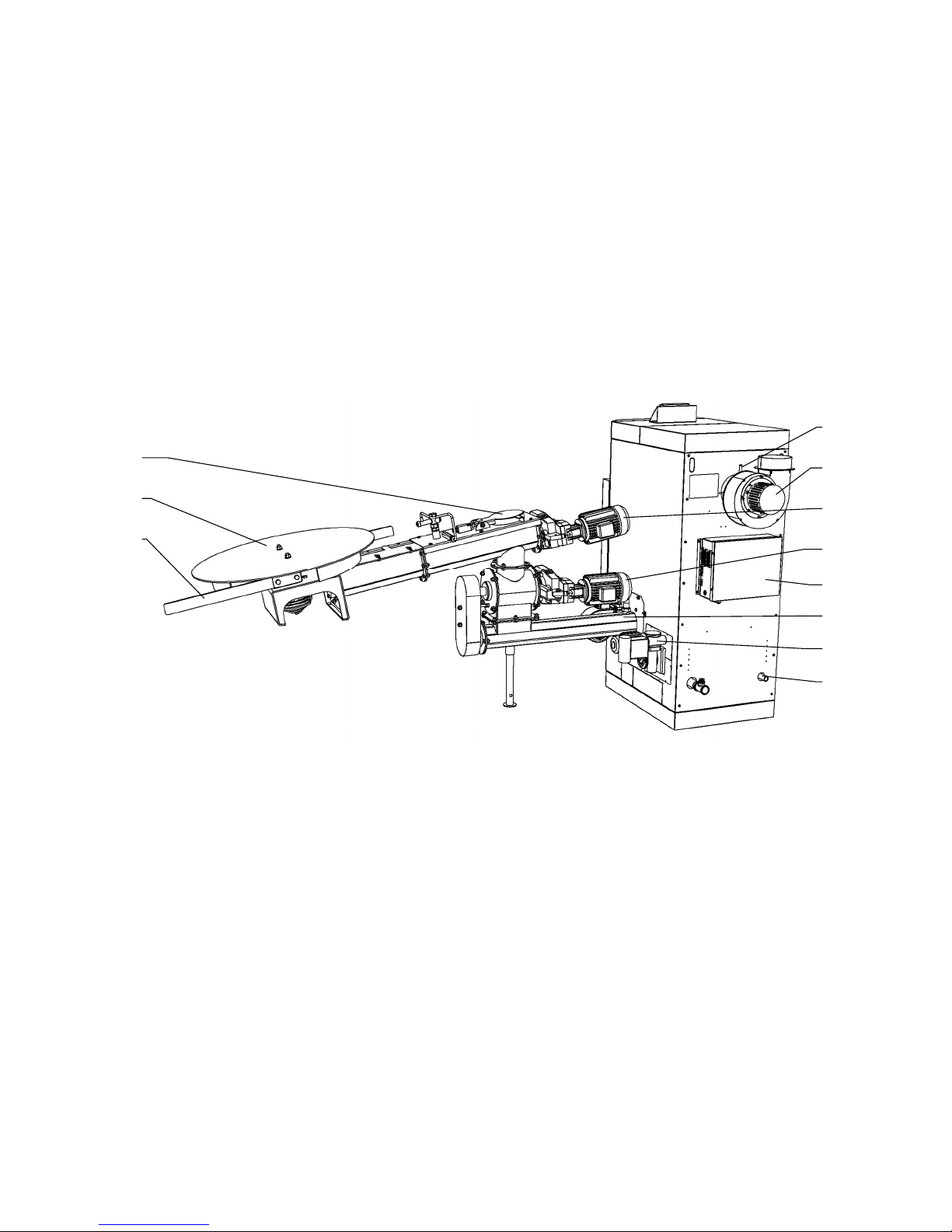
Fig. no. 2 Rear view of the BENEKOV S16 and S26 boiler
17. Cover of feeder from the bunker
18. Stirrer
19. Flexible blades of stirrer
20. Lambda probe
21. Flue gas exhaust
22. Drive of feeder from the bunker
23. Drive of feeder to the boiler
24. Control unit switchboard
25. Feeding to the boiler
26. Automatic heat exchanger cleaning drive
27. Inlet for filling and discharge of the boiler
26
25
23
24
22
21
20
17
18
19
27

10
Fig. no. 3 Front view of the BENEKOV S51 boiler
1. Boiler lid
2. Locking bolt of firing flap
3. Firing flap lever
4. Boiler body
5. Door cover
6. Door cover handle
7. Heat exchanger cleaning door
8. Preparation for ash remover
9. Boiler control unit display
10. Drive of feeder from the bunker
11. Cover of feeder from the bunker
12. Cover limit switch of the bunker feeder
13. Emergency fire extinguishing system
14. Primary air fan
15. Secondary air fan
16. Feeding to the boiler
17. Drive of feeder to the boiler
18. Turnstile chain
19. Feeding from the bunker
1
14 15 16 18
17 19
109
2
3
7
8
11 12 13
6
5
4
Ce manuel convient aux modèles suivants
2
Table des matières
Autres manuels BENEKOV Chaudière


Manuels Chaudière populaires d'autres marques

Vaillant
Vaillant uniSTOR VIH SW GB 500 BES Manuel utilisateur

Radijator
Radijator BIO max 23.1 Manuel utilisateur

Brunner
Brunner BSV 20 Manuel utilisateur

Buderus
Buderus Logamax GB062-24 KDE H V2 Manuel utilisateur

Potterton
Potterton 50e Fiche technique

UTICA BOILERS
UTICA BOILERS TriFire Manuel utilisateur


