Beltrame S2014 Manuel utilisateur

Rev. 4.0
BELTRAME
CENTRO SERVIZI ENERGIA


2
CONTENTS
IMPORTANT INFORMATION................................................................................................................
1. SAFETY INSTRUCTIONS............................................................................................................
1.1 General
1.2 Safety Instrucons
2. DEVICE DESCRIPTION...............................................................................................................
2.1 Introducon
2.2 S2014 Main Specificaons
2.3 CE / EU Compliance
2.4 Overall Dimensions and Fixing Holes...................................................................................
2.5 Applicaon Area
2.6 Basic Inseron Configuraons.............................................................................................
2.7 Hardware.............................................................................................................................
2.8 Control elements and interfaces
2.9 Terminal blocks....................................................................................................................
3. DEVICE CONNECTIONS.............................................................................................................
3.1 Input/Output power connecon / rated data
3.2 Device connecons: CN2 Interface
3.3 Device connecons: CN3 I/O control signals.......................................................................
4. OPERATING MODES.................................................................................................................
5. FUNCTIONS DESCRIPTION........................................................................................................
5.1 So Start
5.2 Compensaon and Droop funcons
5.3 ‘Keep Alive’..........................................................................................................................
5.4 Limiters................................................................................................................................
5.4.1 V/f Limiter
5.4.2 Minimum excitaon current: Under Excitaon limiter
5.4.3 Maximum excitaon current: Over Excitaon limiter..............................................
5.4.4 Minimum capability: Q- limiter
5.4.5 Maximum capability: Q+ limiter..............................................................................
5.4.6 S2014 Configr: Limits status
6. WORKING MODE AND REGULATIONS.......................................................................................
6.1 Automac Voltage Regulator (AVR)....................................................................................
6.2 Field Current Regulaon (FCR)
6.3 Power Factor regulaon (PF)...............................................................................................
6.4 Reacve power regulaon (VAR)
6.5 Digital reference adjustment by calibrator (Up/Down).......................................................
6.6 Digital reference adjustment by analog inputs
4
5
6
7
8
9
10
11
12
13
14
15
16
17
18
19
20
21
22
BELTRAME
CENTRO SERVIZI ENERGIA

7. OPERATOR INTERFACE..............................................................................................................
7.1 Control keypad and display
7.2 Navigang inside the menus
7.3 Parameters Saving...............................................................................................................
7.4 Menù descripon................................................................................................................
7.4.1 Menù “D” - Display (readings)
7.4.2 Menù “R” - References and Regulators
7.4.3 Menù “I” - Inputs and Outputs...............................................................................
7.4.4 Menù “C” - Commands
7.4.5 Menù “P” - Parameters............................................................................................
8. TROUBLE SHOOTING................................................................................................................
8.1 First Inspecon
8.2 Trouble shoong
8.3 Repairing..............................................................................................................................
9. CONNECTION DIAGRAM...........................................................................................................
9.1 Introducon
9.2 Basic S2014 Connecon Diagrams.......................................................................................
9.3 S2014 Connecon Diagrams with Low Voltage Alternator..................................................
9.4 S2014 Connecon Diagrams with Medium Voltage Alternator...........................................
10. BELTRAME CONFIGURATOR: THE PC SOFTWARE.......................................................................
10.1 Connecon between AVR and PC
10.2 Installaon and Communicaon setup
10.3 Parameters seng: P.xxx and procedure.............................................................................
10.4 Parameters Seng: L.xxx and R.xxx.....................................................................................
10.5 Parameters Seng: D.xxx....................................................................................................
10.6 Parameters Seng: O.xxx
10.7 Regulator Windows.............................................................................................................
10.8 Trend window
3
23
24
25
26
27
28
29
30
31
32
33
34
35
36
37
38
BELTRAME
CENTRO SERVIZI ENERGIA

4
Our experience has shown that, if the informaon and recommendaons contained in this Operang Instrucons
are observed, the best possible reliability of our products is assured.
The data contained herein purports solely to describe the product and it is not a warranty of performance or
characteriscs. It is with the best interests of our customers in mind that we constantly strive to improve our
products and keep them abreast of advances in technology. This may, however, lead to discrepancies between a
product and its "Technical Descripon" or "Operang Instrucons".
This document has been carefully prepared and reviewed, however should in spite of this the reader find an error,
he is requested to inform us at his earliest convenience.
It is scarcely possible for the operang instrucons for technical equipment to cover every eventuality, which can
occur in pracce. We would therefore request you to nofy us or our agent in the case of all unusual behavior that
does not appear to be covered by these operang instrucons.
It is pointed out that all local regulaons in force must be observed when connecng and commissioning this
equipment in addion to these operang instrucons.
We cannot accept any responsibility for damage incurred as a result of mishandling the equipment regardless of
whether parcular reference is made in these operang instrucons or not.
All rights with respect to this document, including applicaons for patent and registraon of other industrial
property rights, are reserved. Unauthorized use, in parcular reproducon or making available to third pares, is
prohibited.
IMPORTANT INFORMATION
BELTRAME
CENTRO SERVIZI ENERGIA

5
1. SAFETY INSTRUCTIONS
1.1 General
The safety instrucons shall be followed during installaon, commissioning, operaon and maintenance of the
excitaon system. Read all instrucons carefully before operang the device and keep this manual for future
reference.
1.2 Safety Instrucons
The safety instrucons precede any instrucon in the context where a potenally dangerous situaon may appear.
The safety instrucons are divided into three categories, and each one is introduced by a symbol with its
descripon:
Required Qualificaon
Personnel involved in installaon work and commissioning of the S2014 must be familiar, specially
instructed and informed about the residual danger areas according to the regulaons currently in
force. Operang personnel is not permied to work at the control system. Only specially instructed
personnel must carry out maintenance and repair work. The maintenance personnel must be
informed about the emergency shutdown measures and must be capable of turning off the system
in case of emergency. The maintenance personnel must be familiar with the accident prevenon
measures at their workplace and must be instructed in first aid and firefighng.
It is the owner’s responsibility to ensure that each person involved in the installaon and
commissioning of the S2014 has received the appropriate training or instrucons and has
thoroughly read and clearly understood the safety instrucons in this chapter.
DANGER!
This symbol indicates an imminent danger resulng from mechanical forces or high voltage.
A non-observance leads to life-threatening physical injury or death.
WARNING!
This symbol indicates a dangerous situaon. A non-observance may lead to bad or
life-threatening physical injury or death. It may cause also possible damages to the devices.
NOTICE!
This symbol emphasizes important informaon. A non-observance may cause damage to the
device or to objects close to it.
BELTRAME
CENTRO SERVIZI ENERGIA

6
2. DEVICE DESCRIPTION
2.1 Introducon
S2014 is a last generaon Automac Voltage Regulator for Generators excitaon control. The unit contains the most
advanced microprocessor technology together with IGBT semiconductor technology (Insulated Gate Bipolar
Transistor).
A praccal and simple-to-operate on board panel is used for all control operaons. In addion, user friendly
soware facilitates the commissioning and allows the opmizaon of the performances.
2.2 S2014 Main Specificaons
2.3 CE / EU Compliance
This product has been evaluated and complies with the relevant essenal requirements requested by the EU
legislaon.
It complies with the following EU Direcves:
• LVD 2014/35/EU;
• EMC 2014/30/EU;
• ROHS 2 2011/65/EU.
The harmonized standards used for the evaluaon are:
• EN 50178 - Electronic Equipment for use in Power Installaons;
• EN 61000-6-4 - Electromagnec Compability (EMC), Generic Standards, Emission Standard for Industrial
Environments;
• EN 61000-6-2 - Electromagnec Compability (EMC), Generic Standards, Immunity for Industrial
Environments.
MECHANICAL DETAILS
AMBIENT CONDITION
ELECTRICAL DETAILS
Other
Weight:
Protecon class:
Dimensions (LxWxH)
Power electronics supply:
Excitaon output:
Frequency range:
Accuracy
Voltage inputs
Ambient condion
< ±0.25%
From 10 to 500 Hz
Not insulated
AVR has to be protected against dust, moisture, rain
Temperature range for operaon:
Temperature range for storage:
Vibraon:
Approx. 600 gr
IP2X (limited by fast-on type terminals)
138x58x55 mm
From -20°C to +65°C
From -40°C to +80 °C
5 mm, 2 G, 5<f<150 Hz
3±300 Vac from 10 to 500Hz
Max connuous current 8 A
Current reducon for ambient
temperatures
> 50 °C: 1 A/degree
Forcing (max 10 s): 16 A
BELTRAME
CENTRO SERVIZI ENERGIA

7
2.4 Overall Dimensions and Fixing Holes
2.5 Applicaon Area
This AVR is used for the excitaon of synchronous machines. This unit is suitable for this only applicaon area.
The AVR can manage several regulaons. Among them:
- Voltage regulaon;
- Field Current Regulaon (FCR);
- Power Factor regulaon (PF);
- Reacve power regulaon (VAR).
37
67
6 54
48
129
8
134
142
9
60
54 6
Ø5
BELTRAME
CENTRO SERVIZI ENERGIA

8
In this configuraon the AVR is powered directly from
the generator output (or from an auxiliary winding).
The AVR DC output is feeding the stator of the exciter.
In this configuraon the AVR is powered from a PMG.
The AVR DC output is feeding the stator of the exciter.
This configuraon shows a possible replacement of a
Direct Current excitaon machine.
SM: Synchronous Machine E: Exciter PMG: Permanent-Magnet-Generator D:Direct Current machine
2.6 Basic Inseron Configuraons
The following SLD show some basic inseron configuraons of the S2014.
SM E
AVR
S2014
Vsense
Ig
Power
SM D
AVR
S2014
Vsense
Ig
Power
SM
PMG E
AVR
S2014
Vsense
Ig
Power
BELTRAME
CENTRO SERVIZI ENERGIA
9
Note: The interface is not isolated from the power supply: in order to
connect with a pc or other devices an interface isolator must be used.
2.7 Hardware
Structure:
The device is assembled inside a plasc case with aluminum base, and it is fixed on a heat dissipater.
The connecon terminals are integrated on the top of the circuit boards.
Power electronics:
- The power circuit is designed with IGBT semiconductors.
- A fuse protects the output against short-circuits.
Control elements:
- The operang keys and the display are located on board.
- The communicaon port connector is located on the front of the AVR.
Installaon:
- The site of installaon must be dry and free of dust. The AVR can be installed in vercal or
in horizontal posion.
Mounng:
- The AVR must be installed inside the Generator or inside the control panel in order to obtain protecon
against accidental contacts. To fasten the regulator, use the 4 MA through-screws in two corners holes.
It is recommendable to use self-locking nuts. It is recommended also to bind the regulator back on a
metal plate for beer heat dissipaon.
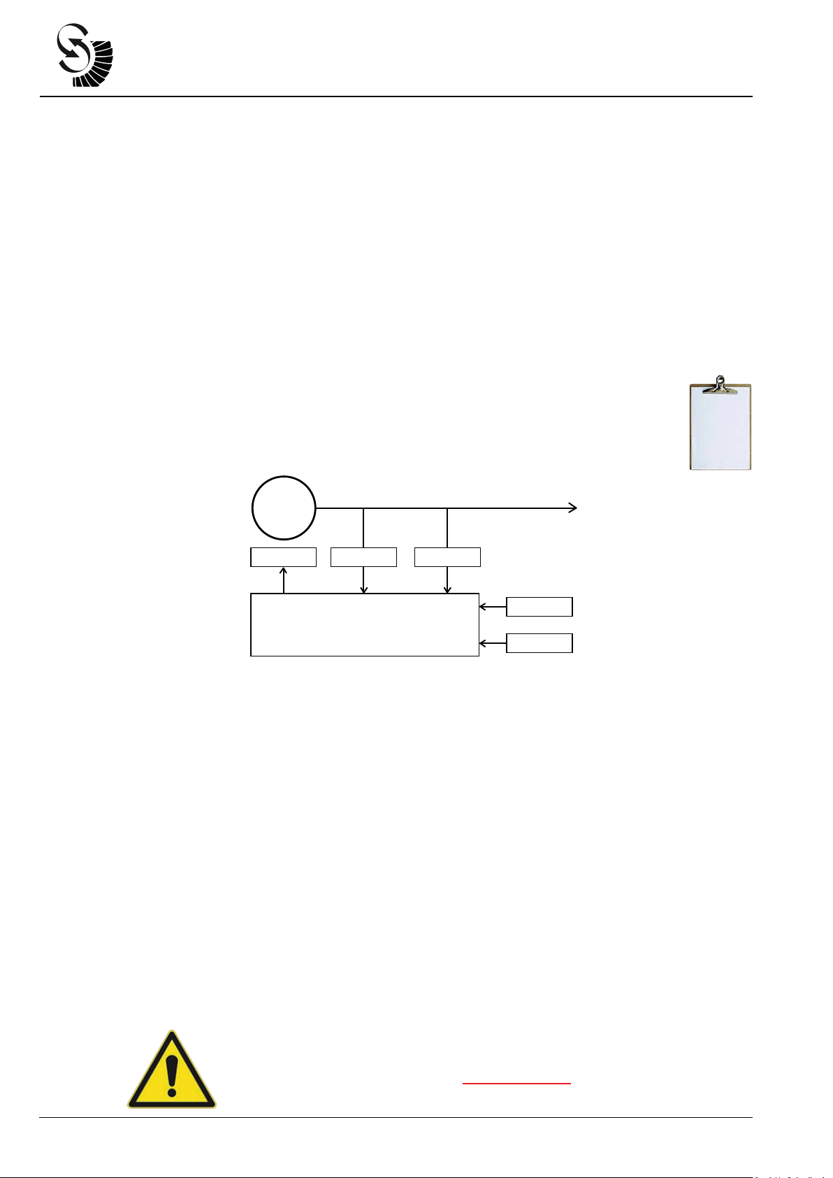
Connecon block diagram:
2.8 Control elements and interfaces
Carrying out sengs on the unit
The displays and the four keys allow complete operaon.
All sengs can be carried out directly on the unit without addional equipment.
• Inputs and outputs configuraon;
• Parameter seng;
• Selecon on the display of the main measured values.
Interface with PC (see the dedicated chapter)
Parameter seng and opmizaon is possible using the user-friendly S2014 Config for Microso Windows. Using
an USB/RS485 cable (made by Beltrame - Oponal), with USB insulator, for the connecon between PC and AVR, is
possible to:
• Configure inputs and outputs;
• Set all parameter;
• Select on the display all the measured values;
• Download, upload, save and open config files;
• … and a lot more.
GENERATOR
Exciter field Current
transformer
Sensing Voltage
transformer
Power supply
3÷300Vac
RS-485 Port
10÷500Hz
S2014
BELTRAME
CENTRO SERVIZI ENERGIA
Autres manuels pour S2014
1
Table des matières
Autres manuels Beltrame Contrôleurs


