
Baxi 755 Instructions de montage

5115012/02
INSTALLER GUIDE
© Baxi Heating U.K. Limited 2006.
Model 755
REMOTE CONTROL
INSET LIVE FUEL EFFECT GAS FIRE
Fitted with a
Fascination fascia
(GC No. 32-811-20)
We trust that this guide gives
sufficient details to enable this
appliance to be installed and
maintained satisfactorily. However, if
further information is required, our
Baxi Fires Division Technical
Helpline will be pleased to help.
Telephone 08706 061 065 (National
call rates apply in the United
Kingdom)
In the Republic of Ireland
Telephone 0044 8706 061 065.
THIS APPLIANCE IS FOR USE WITH
NATURAL GAS (G20).
WHEN CONVERTED USING
CONVERSION KIT NO. 05754M1
THIS
APPLIANCE IS FOR USE WITH
PROPANE GAS (G31).
THIS APPLIANCE IS SUITABLE ONLY
FOR INSTALLATION IN THE UNITED
KINGDOM (GB) AND THE REPUBLIC
OF IRELAND (IE).
INSTALLER: Please leave this guide with the
owner

© Baxi Heating U.K. Limited 2006.
All rights reserved. No part of this publication may be reproduced in any material form
(including photocopying), stored in any medium by electronic means (including in any
retrieval system or database) or transmitted, in any form or by any means, whether
electronic, mechanical, recording or otherwise, without the prior written permission of
the copyright owner.
Applications for the copyright owner's permission to reproduce any part of this
publication should be made, giving details of the proposed use, to the following address:
The Company Secretary, Baxi Heating UK Limited, Pentagon House, Sir Frank Whittle
Road, Derby, DE21 4XA.
Warning: Any person who does any unauthorised act in relation to a copyright work
may be liable to criminal prosecution and civil claims for damages.
Baxi Fires Division, Erdington, Birmingham B24 9QP
www.firesandstoves.co.uk
Because our policy is one of constant development and improvement, details may vary slightly from those
given in this publication
Page 2
INSTALLER GUIDE
© Baxi Heating U.K. Limited 2006.

Safety First.
Baxi Fires Division fires are CE Approved and designed to meet the appropriate British
Standards and Safety Marks.
Quality and Excellence.
All Baxi Fires Division fires are manufactured to the highest standards of quality and
excellence and are manufactured under a BS EN ISO 9001 quality system accepted by
the British Standards Institute.
The Highest Standards
Baxi Fires Division is a member of the Society of British Gas Industries which works to
ensure high standards of safety, quality and performance.
Careful Installation
Baxi Fires Division is a CORGI registered company. All our gas fires must be
installed by a competent CORGI Registered Installer in accordance
with our Installer Guide and should not be fitted directly on to a
carpet or floor of combustible material.
Page 3
INSTALLER GUIDE
© Baxi Heating U.K. Limited 2006.

CONTENTS
Section Heading Page
1. SAFETY 5
2. ACCESSORY LIST 5
3. APPLIANCE DATA 6
4. GENERAL INSTALLATION REQUIREMENTS 7
5. PACK CONTENTS 14
6. FIREPLACE CHECK 15
7. IGNITION CHECK 16
7.1 Fitting batteries to the remote control handset. 16
7.2 Fitting batteries to the heat engine. 17
7.3 Setting the handset and receiver relationship. 17
7.4 Checking the ignition operation. 17
8. GAS SUPPLY CONNECTION 18
9. PREPARING APPLIANCE FOR INSTALLATION 18
10. HOTBOX INSTALLATION 21
11. BURNER & SUPPLY PIPE INSTALLATION 24
12. FITTING THE CERAMIC FUEL EFFECT 26
13. FULL OPERATING CHECKS 26
13.1 Check the handset and burner operation. 26
13.2 Check for spillage. 26
13.3 Flame supervision and spillage monitoring system. 27
14. FASCIA INSTALLATION 28
15. FINAL REVIEW 30
16. SERVICING & PARTS REPLACEMENT 31
16.1 To remove the fascia. 32
16.2 To remove the complete burner unit. 32
16.3 To remove the pilot unit. 33
16.4 To remove the gas tap. 33
16.5 To grease the control tap. 34
16.6 To remove the main burner and injector. 34
16.7 To remove the L.E.D. 35
16.8 To remove the battery holder. 35
16.9 To remove the electronics box. 35
16.10 To remove the appliance from the fireplace. 36
Page 4
INSTALLER GUIDE
© Baxi Heating U.K. Limited 2006.

1. SAFETY
Installer
Before continuing any further with the installation of this appliance please read the
following guide to manual handling:
! The lifting weight of this appliance is as below:
Model Weight (kg)
Fascination 16.5
! One person should be sufficient to lift the fire. If for any reason this weight is
considered too heavy then obtain assistance.
!
When lifting always keep your back straight. Bend your legs and not your back.
! Avoid twisting at the waist. It is better to reposition your feet.
! Avoid upper body/top heavy bending. Do not lean forward or sideways whilst
handling the fire.
!
Always grip with the palm of the hand. Do not use the tips of fingers for support.
! Always keep the fire as close to the body as possible. This will minimise the
cantilever action.
! Use gloves to provide additional grip.
! Always use assistance if required.
2. ACCESSORY LIST
The following accessories are available: -
Description Part Number
Pre cast and clay flue block spacer kit 05654K1
LPG conversion kit 05754M1
Page 5
INSTALLER GUIDE
© Baxi Heating U.K. Limited 2006.

3. APPLIANCE DATA
* When converted using conversion kit number 05754M1.
The appliance data label is located on a plate at the base of the fire. This can be seen by
lowering the bottom front cover of the fascia.
The efficiency of this appliance has been measured as specified in BS 7977 - 1 and the
result is as below :
Model
Efficiency % (Gross)
Fascination. 48
Fascination when converted to LPG. 50
The gross calorific value of the fuel has been used for this efficiency calculation. The
test data from which it has been calculated has been certified by Advantica Certification
services (0087). The efficiency value may be used in the UK Government's Standard
Assessment Procedure (SAP) for energy rating of dwellings.
The convertion of net efficiency to gross was achieved by
multiplying the net efficiency
by the following conversion factor from Table E3 of SAP 2005, rounding down to the
nearest whole number.
Page 6
INSTALLER GUIDE
© Baxi Heating U.K. Limited 2006.
Gas Natural (G20) Propane (G31)*
Inlet Pressure 20mbar 37mbar
Input Max. (Gross) 5.5kW (18,766 Btu/h) 5.0kW (17,060 Btu/h)
Input - Min. (Gross) 3.1kW (10,577 Btu/h) 4.6kW (15,695 Btu/h)
Inlet Test Pressure (Cold) 20.0 ± 1.0mbar (8.0 ± 0.4in
w.g.)
37.0 ± 1.0mbar (14.85 ±
0.4in w.g.)
Gas Connection 8mm pipe 8mm pipe
Burner Injector Stereomatic Cat. 82 Size 065 StereomaticSize 110
Pilot & Atmosphere Sensing
Device Copreci Ref. O.D.S
21500/194
Copreci Ref. O.D.S
21500/194 Fitted with RBM
180 - 02 injector
Ignition Electronic Electronic
Aeration Non-adjustable Non-adjustable

This product uses fuel effect pieces containing Refractory Ceramic Fibres (RCF),
which are man-made vitreous silicate fibres. Excessive exposure to these materials
may cause irritation to eyes, skin and respiratory tract. Consequently, it is
important to take care when handling these articles to ensure that the release of
dust is kept to a minimum. To ensure that the release of fibres from these RCF
articles is kept to a minimum, during installation and servicing we recommend that
you use a HEPA filtered vacuum to remove any dust and soot accumulated in and
around the fire before and after working on the fire. When replacing these articles
we recommend that the replaced items are not broken up, but are sealed within a
heavy duty polythene bag, clearly labelled as RCF waste. RCF waste is classed as a
stable, non-reactive hazardous waste and may be disposed at a landfill licensed to
accept such waste. Protective clothing is not required when handling these articles,
but we recommend you follow the normal hygiene rules of not smoking, eating or
drinking in the work area and always wash your hands before eating or drinking.
This appliance does not contain any component manufactured from asbestos or
asbestos related products.
4. GENERAL INSTALLATION REQUIREMENTS
4.1 The installation must be in accordance with these instructions.
For the user’s protection, in the United Kingdom it is the law that all gas appliances are
installed by competent persons in accordance with the current edition of the Gas Safety
(Installation and Use) Regulations. Failure to install the appliance correctly could lead
to prosecution. The Council for the Registration of Gas Installers (CORGI) requires its
members to work to recognised standards.
In the United Kingdom the installation must also be in accordance with:
All the relevant parts of local regulations.
All relevant codes of practice.
The relevant parts of the current editions of the following British Standards:-
BS 715
BS EN 1856 Part 1
BS 1251
BS EN 1858 which replaces BS 1289 Part 1
BS EN 1806 which replaces BS 1289 Part 2
BS EN 1856 Part 1 which replaces BS 4543 Part 2
Page 7
INSTALLER GUIDE
© Baxi Heating U.K. Limited 2006.
Gas Conversion factor from net to gross efficiency
Natural Gas 0.901
LPG 0.921

BS 5440 Part 1
BS 5440 Part 2
BS 5871 Part 2
BS 6461 Part 1
BS 6891
BS 8303
In England and Wales, the current edition of the Building Regulations issued by the
Department of the Environment and the Welsh Office
In Scotland, the current edition of the Building Standards (Scotland) Regulations issued
by the Scottish Executive.
In Northern Ireland, the current edition of the Building regulations (Northern Ireland)
issued by the Department of
the Environment for Northern Ireland.
In the republic of Ireland the installation must also conform to the relevant parts of:
a) The current edition of IS 813 “Domestic gas installations”
b) All relevant national and local rules in force.
Where no specific instructions are given, reference should be made to the relevant
British Standard Code of Practice.
4.2
In the United Kingdom, as supplied, the appliance can be installed in the following
situations:
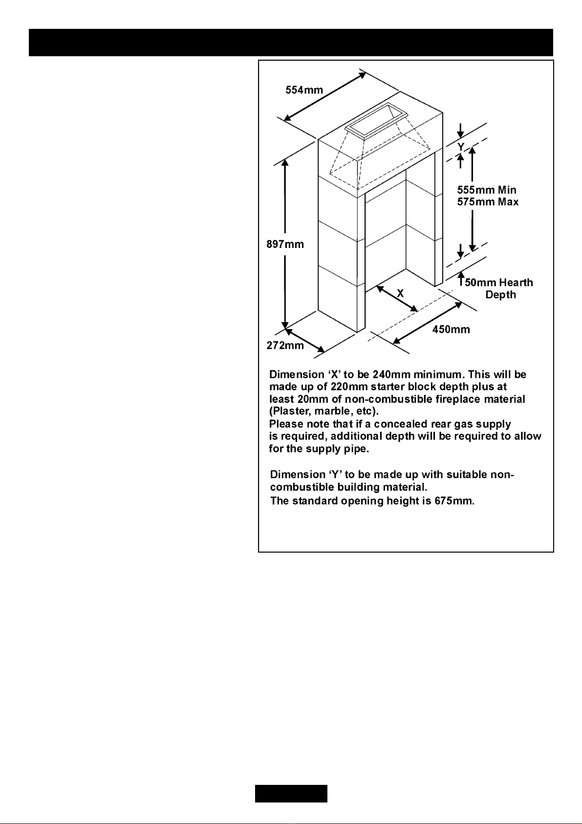
4.2.1 To a fireplace complete with surround and hearth as shown in figure 1 and
complying with BS1251 after removal of the fireback and sufficient material behind the
fireback for a debris
catchment space. The
required fireplace, hearth,
debris catchment area and
clearance dimensions are
shown in figure 1.
4.2.1.1 ‘Hole-in-the-wall’
installations.
It is recommended that a
hearth should be installed
as in figure 1. If a hearth is
not fitted, the fire must be
installed so that the
distance from the base of
the fireplace opening in the
wall to the finished floor
level is at least 85mm.
Where there is no floor
Page 8
INSTALLER GUIDE
© Baxi Heating U.K. Limited 2006.
Figure 1. Hearth and fireplace opening dimensions

covering or carpet and the floor is of
a type that is likely to be covered in
such a way in the future then the
distance from the base of the
fireplace opening in the wall to the
floor level should be increased to at
least 160mm. The minimum shelf
height will have to be taken from the
base of the fireplace opening.
4.2.2 To a fireplace incorporating a
metal flue box complying with the
constructional requirements of
BS 715 and BS EN 1856 Part 1. The
dimensions of the flue box must
conform to those shown in figure 2.
4.2.3 A precast concrete or clay flue
block system conforming to BS EN
1858 or BS 1289 with dimensions as
in figure 3 or using a 05654K1 spacer
kit. (Installation Instructions part
number 3003095). The current versions of BS1289 and BS EN 1858 recommend that
there should be an air space or insulation between the flue blocks and the plaster
because heat transfer may cause cracking on directly plastered flues. However, generally
this appliance is suitable for installations under all circumstances unless there is a
history of cracking problems.
Remember that faults such as cracking may be caused by poorly built and restrictive
flues, e.g. mortar extrusions, too many bends, flue heights below three metres,
restrictive terminations etc (See figure 3).
4.2.4 If the fireplace opening is greater than the acceptable dimensions given in this
guide, do not use the back of a fire surround or marble to reduce the opening. This may
cause cracking of the surround back or marble.
4.3 Suitable flues and minimum flue sizes are as follows: -
It should be noted that, as with many appliances, sharp bends or horizontal runs in
metal flues at the top of the system can be a cause of problems in these types of
installation.
! 225mm x 225mm conventional brick flue.
! 175mm diameter lined brick or stone flue.
!
200mm diameter factory made insulated flue manufactured to the current edition of
BS EN 1859 or BS 4543.
! 175mm diameter flue pipe. See BS6461 Part 1 for suitable materials.
Page 9
INSTALLER GUIDE
© Baxi Heating U.K. Limited 2006.
Figure 2. Metal flue box
! Single wall, twin wall or flexible
flue liner with a minimum diameter of
125mm. The materials to be used are
stainless steel or aluminium as
specified in BS EN 1856 Part 1. The
liner must be sealed to the
surrounding area above the fireplace
opening and to the top of the chimney.
An approved terminal must be fitted.
! A properly constructed precast
concrete or clay flue system
conforming to BS1289 or BS EN
1858. This system is only suitable if
the conditions stated in section 4.2.3
are met.
4.4 The flue must conform to BS
5440: Part 1 in design and installation.
The flue, measured from the bottom
of the fireplace opening to the bottom
of the terminal, shall be not less than
3m in actual vertical height. When
calculated in accordance with BS
5440: Part 1 Annex A, the minimum
equivalent height of the flue shall be
2.0m of 125mm-dia. flue pipe.
4.5 The flue must not be used for
any other appliance or application.
4.6
Any chimney damper or restrictor should be removed. If removal is not possible,
they must be secured in the open position.
4.7
If the appliance is intended to be installed to a chimney that was previously used
for solid fuel, the flue must be swept clean prior to installation. All flues should be
inspected for soundness and freedom from blockages.
4.8 If the fireplace opening is an underfloor draught type, it must be sealed to stop
any draughts.
4.9 The appliance must be mounted behind a non-combustible hearth unless the
conditions in section 4.2.3 are met (N.B. conglomerate marble hearths are considered as
non-combustible). The appliance can be fitted to a purpose made proprietary class “O”-
Page 10
INSTALLER GUIDE
© Baxi Heating U.K. Limited 2006.
Figure 3. Precast or clay flue block system
dimensions
Table des matières
Autres manuels Baxi Système de chauffage

Baxi
Baxi Bermuda PW5 Deluxe Instructions de fonctionnement

Baxi
Baxi Valor Fires 540 Manuel utilisateur

Baxi
Baxi GAVINA 20 GT Guide de configuration

Baxi
Baxi Main 12 HE Mode d’emploi

Baxi
Baxi Assure Horizontal SHRU Manuel

Baxi
Baxi Assure FGHR Manuel utilisateur

Baxi
Baxi LUNA SAT Manuel utilisateur

Baxi
Baxi Bermuda Inset 3 BS Super Instructions de fonctionnement

Baxi
Baxi Senertec Dachs Pro 20 ST Instructions d'installation

Baxi
Baxi SILA RCV 300 Manuel utilisateur


