Balcrank FUSION 3110-013 Guide de l'utilisateur

SERVICE BULLETIN SB3063
Rev A 12/08
Thoroughly read and understand this manual before
installing, operating or servicing this equipment.
ADMINISTRATION SETUP MANUAL
FUSION
DISTRIBUTED CONTROL
FLUID MANAGEMENT SYSTEM
®
Model 3110-013
Distributed Control
Keypad
Zone Keypad
Zone Keypad

Disclaimer
The user/purchaser is expected to read and understand the information provided in this
manual, follow any listed Safety Precautions and Instructions and keep this manual with the
equipment for future reference.
The information in this manual has been carefully checked and is believed to be entirely
reliable and consistent with the product described. However, no responsibility is assumed
for inaccuracies, nor does Balcrank Products, Inc. assume any liability arising out of the
application and use of the equipment described.
Should the equipment be used in a manner not specied by Balcrank Products, Inc., the
protection provided by the equipment may be impaired.
Questions or Service Assistance
If you have questions regarding the product or this document contact:
Balcrank Products, Inc.
115 Reems Creek Rd.
Weaverville, NC 28787
Telephone: (828) 645-4261
(800) 747-5300
Fax: (828) 658-0840
(800) 763-0840
On the Web: www.balcrank.com
or call your local Balcrank Products, Inc. representative.
Product Identication Information
Record the product identication numbers from the nameplate here.
Model Number _______
Serial Number _____________
Tag Number _______________(if applicable)

Index
Introduction ........................................................................................................................... 4
Master Keypad to Host/PC Connection ................................................................................ 5
System Overview ................................................................................................................. 6
System Operation ................................................................................................................. 7
System Information ............................................................................................................ 10
System Reports................................................................................................................... 12
User Management............................................................................................................... 14
File Management ................................................................................................................ 16
System Setup...................................................................................................................... 21
System Entity ..................................................................................................................... 26
System Product Tree Conguration ................................................................................... 29
System Network Tree Conguration ................................................................................... 30
System Network Installation Process.................................................................................. 32
Process to Modify/Add/Delete Users .................................................................................. 34
Process to Test MK/PC Communications............................................................................ 35
Process to Add/Delete a Hose – Meter............................................................................... 36
Trouble Shooting Guide ..................................................................................................... 37
Communications Flow......................................................................................................... 41

4
Introduction
The Balcrank Distributed Control Fluid Management System is designed to control and
monitor the consumption and inventory balances of automotive uid products with minimal
installation and programming costs. Balcrank has utilized its years of expertise in the Auto-
mated Meter Reading market to develop a control system utilizing RF communications.
The Distributed Control RF Fluid management system requires one Distributed Control
keypad and one Zone keypad. The Distributed Control keypad handles serial communi-
cation between the PC/Host Server and RF communication to the Zone keypads in the
system. The system veries operator pin number, validates work order number, dispense
uid quantities and valid hose for uid required.
The Distributed Control keypad can communicate with up to 12 Zone keypads that can be
positioned to best support the workow of the facility. The system supports up to 16 tanks
and 16 uids as part of the system conguration. The system supports 250 unique operator
IDs and pin numbers
.
The system utilizes spread spectrum frequency hopping RF technology to prevent com-
munication problems with other equipment in the facility. The RF system will look for a clear
channel for transmission to insure that there is reliable communications at all times. Com-
munication distances are typically up to 300 feet or more and there is a remote antenna
available for situations where multiple buildings are involved in the installation.
The PC is used to congure the system, maintain system data and enter work orders.
The service desk would utilize the PC to enter a work order selecting the uid and quan-
tity required. The PC can stack as many work orders as required, based only on the local
storage of the PC. There is no need to predetermine where the work is going to occur. This
allows the exibility to service a vehicle at any open bay and select a hose to use when the
work is going to be performed. When the work order is going to be performed the service
personnel simply enters their pin number, work order and hose that is going to be used at
the Zone keypad.
There are a number of system utilization reports by user; uid type, tank or meters available
for the management of the system.
A unique, patented feature of the control system is that the dispense trigger of the RF meter
is locked until authorization from the keypad is received. After the dispense is completed,
the user can top off the dispense and the actual amount used is sent back to the keypad
and the meter returns to the locked status. Additionally, the meter can be installed on por-
table dolly systems offering control and monitoring of often high- cost lubrication products.

5
Distributed Control Keypad to Host/PC Connections:
There are two cables with 9 pin connectors attached to the Distributed Control keypad.
The 9-pin connector on the bottom of the Distributed Control Keypad is for connection to
the PC.
The cable marked with an “O” is for connection to an optional printer.
The cable without any markings is for the host connection. All cables have the same pin
outs listed below.
Connections:
Distributed Control Keypad Plugs (9-pin) RS-232 PC or Host plug (9-pin)
RS-232
PIN No. 2 (TXD)............................................................PIN No. 3 (RXD)
PIN No. 3 (RXD) .......................................................... PIN No. 2 (TXD)
PIN No. 7 (GND)...........................................................PIN No. 7 (GND)
Max. cable length: at 1200 Baud = 150 m.
at 9600 Baud = 100 m.
Distributed Control Keypad
9-Pin for PC
Connection “O” indicates
cable for printer
output
Host

6
System Overview
The Distributed Control keypad acts as the communications director for the RF communica-
tions. It handles all communications between the Zone keypads and the PC or Host. There
are no Operator menus associated with the Distributed Control Keypad.
System Congurations:
• Distributed Control/Dispense with PC Operation
In this conguration the PC is used to congure the system entities and install the network.
The PC will be used to enter work orders for processing and provide the queuing for future
processing. When operator processes a work order the PC will validate the work order
number and provide the uid and amount to be dispensed. The results of the dispense will
then be stored on the PC.
• Distributed Control/Dispense with Host Operation
In this conguration the PC is used to congure the system entities and install the network.
The results of the dispense will then be stored on the PC. The Host will be used to enter
work orders for processing and provide the queuing for future processing. When operator
processes a work order the Host will validate the work order number and provide the uid
and amount to be dispensed.
Note: Dispense keypads can be used to access only the meters that are associated with
that dispense keypad. All system users can access each of the dispense keypads.
An external printer can be added to either conguration.
Distributed Control
Keypad
Zone Keypad
Zone Keypad

7
System Operation
System Logon Screen
To Logon on to the OMS Distributed Control System, enter the 4-digit system password and
click he LogOn button.
The system password is initially set to 0000 and can be changed using the system
initialization screen if desired.

8
Work Orders Screen
After logon is complete the work orders screen will be displayed. The Main menu will be
displayed along the left side of the screen. To see more of the main menu selections you
can scroll up and down using the bar on the right side of the screen. To select an option
from the Main menu, click on the desired item. To return to the Work Order screen, click on
the LOGO in the upper left hand corner of the current display screen at any time.
The Work Order screen allows you to select the time frame of historical information to be
displayed. Use the pull down menu to select a different display options and click OK.
9
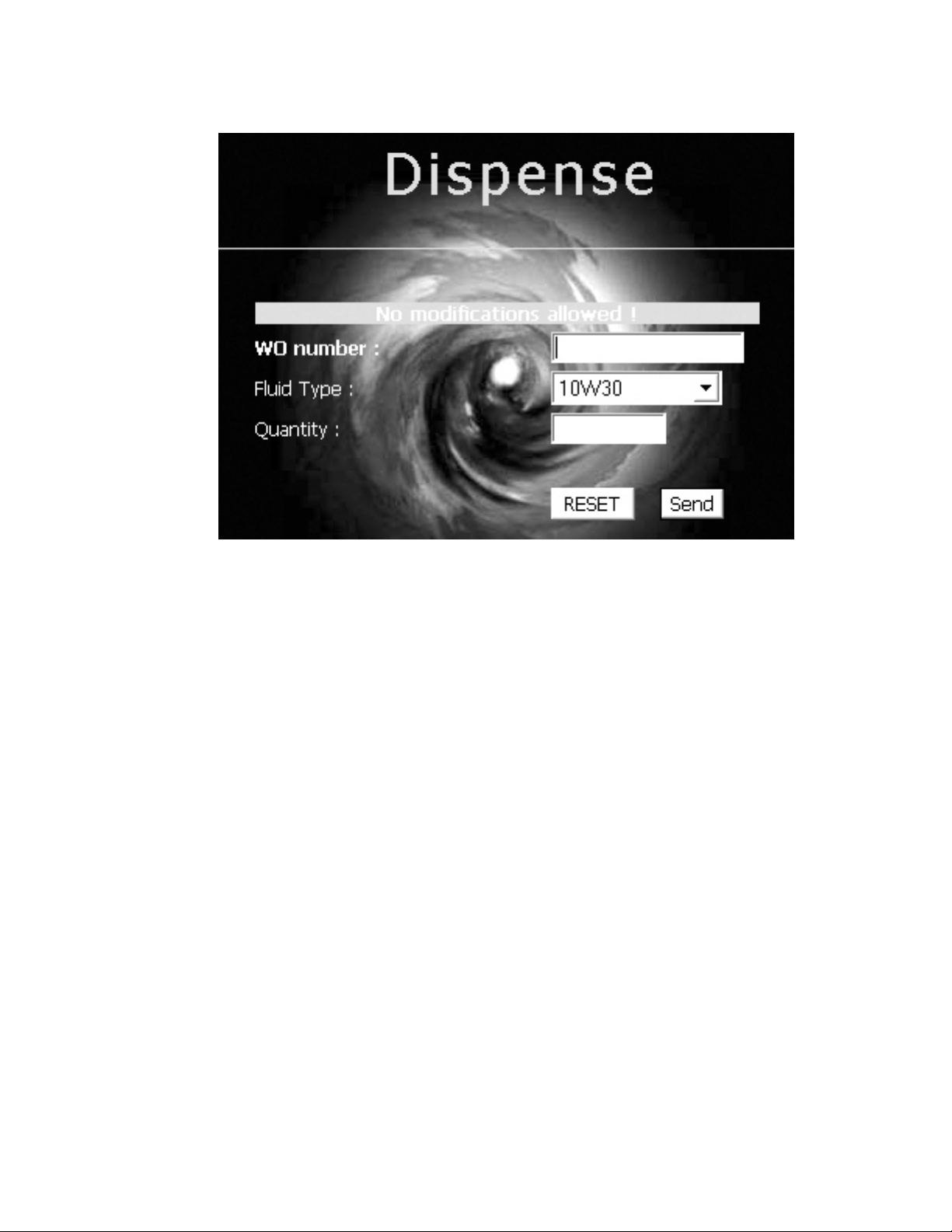
Dispense Screen
The dispense screen is used to enter work orders into the system. This would be the
normal operation screen used.
Operation:
1. Enter the work order number
2. Select the desired uid type from the pull down menu
3. Enter the uid quantity
4. Click the Send Button
To abort the Work Order entry in process, click the reset button.
Note: The quantity is based on the Tank Unit. The meter must be programmed to dispense
in the same unit as the tank.
The queuing feature of the system allows for work orders to be entered into the system and
have the dispense performed at some point in the future. There is no need to pre-determine
or select the hose to be used for dispense before it is going to occur. The operator will
select the work order to be worked on from the zone keypad. The hose selected at that time
will be veried for the correct uid and the dispense quantity will be sent to the meter.
See the Zone Keypad SBxxxx for complete dispense operation.

10
System Information
Work Orders Screen
The Work Order screen allows you to select the time frame of historical information to be
displayed. Use the pull down menu to select a different display option.
Tank Level Screen
The Tank Level screen is for informational purposes only. It shows graphically the level of
the uid in the tank, uid type and tank capacity.
Autres manuels pour FUSION 3110-013
1
Table des matières
Autres manuels Balcrank Système de contrôle


