babala Hydro-Pro Manuel utilisateur

Hydro-Pro
Environmental Control System
www.babala-hydroponics.cn www.pro-leaf.com
Instruction Manual

Contents
I.
II.
III.
IV.
V.
Overview of Hydro-Pro System
Specifications of Hydro-Pro Series Products
Warings & Cautions / Avertissement & Précautions
Installation Instructions
Installation Diagram
VI.
VII. Operation Instructions
1
Interface Instructions

I. Overview of Hydro-Pro System
Pro-Leaf Hydro-Pro is the most complete and intelligent environment control system that applies
to professional indoor growth on the market. Featuring with CO23-in-one sensor (Temp/Humid/-
CO2/Light), Temperature and humidity sensor(with photocell), master controller, LDA-1 Light
adapter and AC station control modules, it can control up to 2 channels of light (using LDA-1
adapter), 8 sensors (4 CO23-in-one sensors and 4 humid and temp sensors), 4 temperature
control devices, 4 humidity control devices and 4 CO2Generators. Almost all the device settings
are programmable via the master controller. ( The devices can be programmed on the master
controller).
Independent day and night control parameters can be set to maintain the optimal environmental
conditions around the clock for the crops to grow indoors. Hydro-Pro's 3-in-one sensor helps you
to monitor temperature, humidity, and CO2level. You can install the additional sensors to you
help you better control and monitor the growing environment of the plants.
You can easily set up daily lighting and specially designed light management in a convenient
manner. Hydro-Pro allows you to select the type of light (LED or HID) to be controlled and can
simultaneously employ 2 channels of independent or interlocked light control logic in different
modes to create multiple lighting layouts and growth spectra required for plant growth. This
system can efficiently monitor the temperature of the lighting system in operation, to which it can
control accordingly with advanced functions like auto-dimming, overheat shutdown, sunrise, and
sunset simulation.
The Hydro-Pro master controller has 10 control signals (24V AC) output for different devices. By
connecting to the contactor panel board in the distribution box, the signal line (24V AC) can
control devices like Air Conditioner, Heater, humidifier, dehumidifier, and non-dimmable light
lines. The independent AC station can also be connected through Mobus RS485 to control CO2
supplement devices. Or it can control the air conditioner, heater, humidifier, dehumidifier, and
other devices through Mobus protocol RS485. Hydro-Pro is an intelligent and flexible control
system that provides growers a complete indoor gardening solution for maximum yield.
1. Follow all local and national electrical codes for installation requirements.
2. Hydro-Pro is specially designed for indoor use only. Please use our Hydro-Pro accessories to
ensure its best performance.
WARNINGS:
2

II. Specifications of Hydro-Pro Series Products
Hydro-Pro Master Controller
Product name Hydro-Pro Master Controller
Input Voltage 120VAC±15VAC, 60Hz, 1A (can be customized)
220VAC±15VAC, 50/60Hz, 1A (can be customized)
AC signal output (PORT) 10-channel signal output: AC24V/0.1A
Other signal output ports (RJ12) RJ12 x 4, 4-channel RS485 communication
Signal line output: DC24V, 1.0A
Network port RJ45
Dimensions 14” H x 17” W x 4” D (excluding length of power cable)
Power cord length ≈2m/6.5ft
Net weight 6.6 lbs
Gross weight 9.3 lbs
Package size 370x330x145mm / 14.6"x13.0"x5.7" (1 unit/box)
Accessories
Self-tapping screws * 4;
Ring Expansion Screw * 4;
Temperature and humidity sensor probe * 1
AC Station module * 1
RJ12 network extension connector * 1
RS485 communication extension cable 5.0m * 1
3

CO2, Humidity & Temp Sensor Humidity & Temperature Sensor
Main parameters Default values
Gas detected CO2
Working voltage DC24V
Working current 30mA
CO2range 0~6000ppm
CO2accuracy ±(30ppm+3%)
Humidity range 0-100%RH
Humidity accuracy ±2%RH
Temperature range 0~70℃
Temperature accuracy ±0.5℃
Maximum quantity 4pcs per unit
Communication mode RS485 [Modbus-RTU]
Light Sensor Photocell
Main parameters Default values
Working voltage DC24V
Working current <10mA
Humidity range 0-100%RH
Humidity accuracy ±2%RH
Temperature range 0~70℃
Temperature accuracy ±0.5℃
Maximum quantity 4pcs per set
Communication mode RS485 [Modbus-RTU]
Light Sensor Photocell
4

AC Station socket module Light control module
Main parameters Default values
Input Voltage AC110V 60Hz
Output Voltage AC110V/60Hz/MAX10
Maximum power <1100W
Communication terminal RJ12 connector
Indicator Green LED
Maximum connections
quantity 32pcs
Communication Mode RS485(Modbus-RTU)
Main parameters Default values
Input Voltage DC24V
Output Voltage 0~10V (DC)
Communication terminal RJ12 connector
Indicator Green LED
Maximum connections
per channel 20pcs
Communication Mode RS485(Modbus-RTU)
5

Warning: Please cut off the power when wiring
Avertissement: couper l'alimentation électrique pendant le câblage
Cautions:Please read this manual carefully before operating the Hydro-Pro Master Controller.
Précautions :Lisez attentivement ce manuel avant d'utiliser le Contrôleur principal Hydro Pro.
Warning: Do not place metal objects such as paper clips and tools in the controller to prevent an
electrical shock hazard.
Avertissement: Ne placez pas d'objets métalliques tels que des trombones et des outils dans le
Contrôleur afin d'éviter un risque de choc électrique.
Cautions:Before plugging in the Hydro-Pro Master Controller, check whether the voltage of the
socket is consistent with the parameter described.
Précautions : Avant d'insérer le Contrôleur principal Hydro pro, vérifiez que la tension de la prise
correspond aux paramètres décrits.
Cautions:After the equipment is installed, perform the start-up test before operating it properly.
Précautions :Après l'installation de l'équipement, effectuer l'essai de démarrage avant le bon
fonctionnement.
IV. Installation Instructions
Before use, the Hydro-Pro Master Controller should be properly secured to a wall. The air intake
and exhaust of the controller must be kept clear, and there must be no obstruction. Keep the
environment where the product is used well ventilated. Do not place flammable and explosive
materials, such as gasoline near the equipment.
1. Attach the controller to the wall using the complimentary accessories
III. Warings & Cautions / Avertissement & Précautions
6

7
3. Open the cover of the controller, and connect the corresponding devices accordingly.
Heat Cool Humidify Humidify Dehumidify
01 02 03 04 05
06 07 08 09 10
Dehumidify Light-1 Light-2 AlarmAlarm
2. Loosen the screw on the controller.
Counterclockwise
1. Connect the Hydro-Pro Master Controller to the power supply (Please refer to the parameter
table to ensure that the parameters of the power supply are consistent); set the required parame-
ters on the master controller properly before using it.
2. The working status of the Hydro-Pro Master Controller will be displayed with the status sign on
its interface; get familiar with the specified meaning of each sign.
3. Make sure that the probes (CO2sensor probe, and temperature and humidity sensor) are
connected to the probe socket on the bottom of the Hydro-Pro Master Controller, and check if the
connector is properly inserted. Place the probe of the light sensor in the place to be measured,
with its front side facing the light source unobstructed.
WARNING: Do not disassemble the Hydro-Pro Master Controller before you are familiar with it.
Please read the manual first. In case of any questions, consult your dealer. (To ensure safety,
please read this manual carefully and follow the instructions before installation. If you have any
questions, please contact us or consult with your dealer)
Note:
8
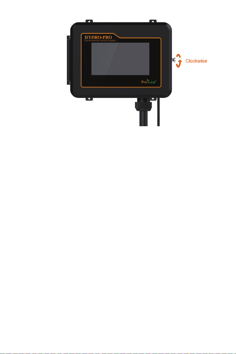
4. Close the cover after the installation is completed, and tighten the screw on the controller.
Clockwise

V. Installation Diagram
4x CO2 Sensor
Lights
Lights
Net
Power
AC 110V
USB TF Reset
4x Humidity & Temp Sensor
CO2 TankCO2 Generator Fan
Devices
Devices
Distribution box
Dehumidifier
9
Table des matières


