AVIAIR AVI35 Manuel utilisateur

Installation and User Manual

2

3
Designed and assembled in Canada by Distribution Avi-Air Inc.
Modèle : AVI35W
Intake Ventilator : 1-60Hz 240V 1,9A RPM 3255
CSA 172512
Exhaust Ventilator : 1-60Hz 240V 1,9A RPM 3255
CSA 172512
Patent Pending USPTO 62/366,657
www.distributionavi-air.com
114 Rang Roy 450 375 5539
Saint-Alphonse de Granby 450 531 9865
J0E2A0 sales@distributionavi-air.com
Qc, Canada

4
Table of content
Electrician’s note and diagram……………………………….………..…Page 5
Installation Guide…………………………………………….……….…….Page 17
Warranty………………………………………………….…….….…...…….Page 21

5
Electrician's Notes
and Connection
Diagram
The manufacturer recommends that the electrical
connection be performed by a qualified electrician.
6
Warnings and precautions
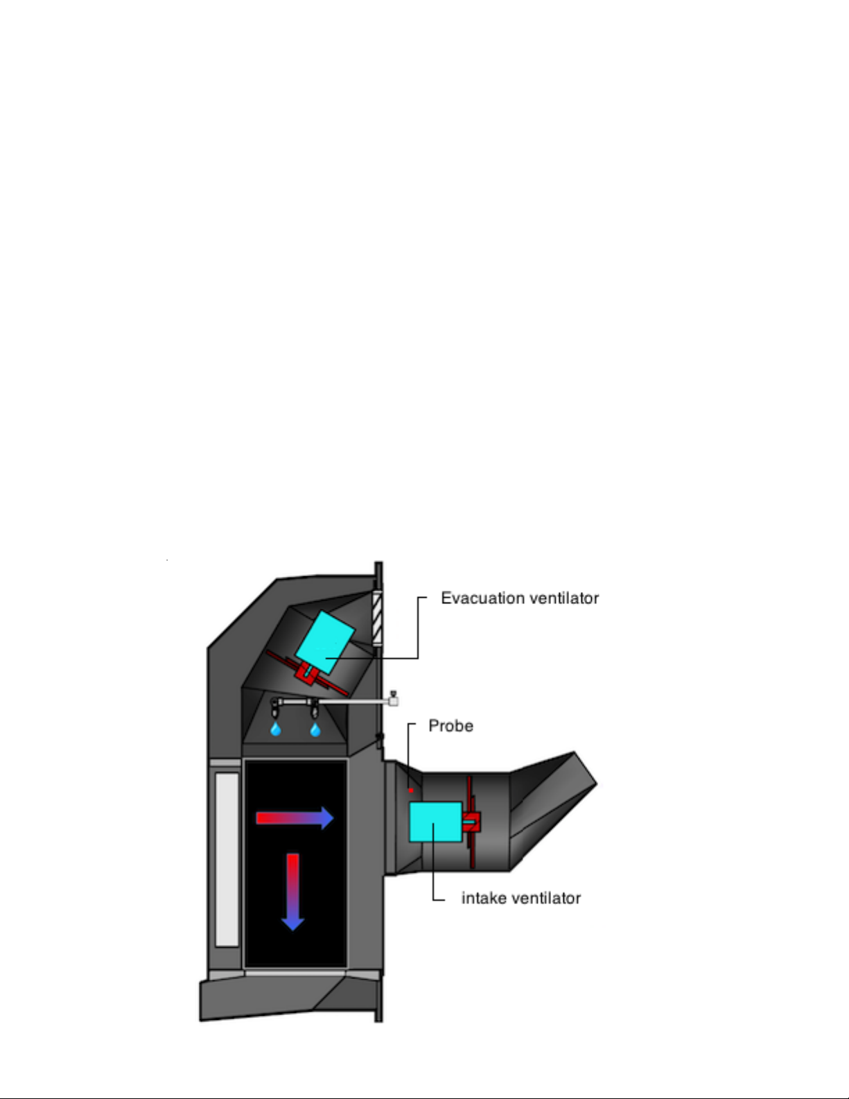
Recovery probe
Only one probe per stage is used per regulator. The probe is assigned to the INTAKE
ventilator of the recuperator.
The INTAKE fan will be activated based on this probe when the Avi35 is in recovery mode.
If more than one recuperator is connected in series to the regulator, the manufacturer
recommends to place the probe on the Avi35 recuperator which will be used during the
departure of a flock, or the one which will work in the first place.
The manufacturer recommends installing the probe at one end of the INTAKE fan leg support.
The probe should be secured at a minimum distance of 8 cm from the motor.

7
Warnings and precautions
DPDT relay used for defrost cycles in
Maximus
and AVI-28
The controller switch corresponding to the relay energizing the DPDT contactors (not included)
is automatically deactivated to prevent human error. Automatic deactivation of the switch
prevents undesired fan rotation inversions caused by the user.
DPDT contactors are energized only automatically by the controller.
Automatic Reversal of INTAKE Fan Rotation will not occur if the variable board switch
associated with the INTAKE fans is not set to automatic position.
The manufacturer recommends to check the reversal of rotation functions of the INTAKE fan at
the first start of the Avi35.
INTERLOCK double relays used for defrost cycles in
Multi-Zone
Genius
The GENIUS controller will used two relays to energize the corresponding interlock double
relay contactors (not included) that activates the defrost cycles. Therefore, the first relay will
activate the fan clockwise, whereas the second relay will activate the fan counterclock wise.
The manufacturer recommends to check the reversal of rotation functions of the INTAKE fan at
the first start of the Avi35.

8
Warnings and precautions
Automated rinsing system
The manufacturer recommends the use of a centrifugal booster pump (not included) providing
a minimum of 10 gpm at 50 psi to provide sufficient water to the flushing system.
All regulators in the same building use the same centrifugal booster pump.
Each solenoid valve 240V must be connected to a single ON / OFF relay of the regulator.
Each valve has its own circuit.
MULTIFAN MOTOR SPECIFICATION

9
Warnings and precautions
INTAKE AND
EXHAUST VENTILATORS
The manufacturer recommends consulting the regulator installation guide for connection to the
variable board and the ON / OFF relays.
The manufacturer recommends a maximum of six Avi35 pickups by Gev2 accessory card
amplifier for Genius Itouch.
The manufacturer recommends a maximum of three Avi 35 per variable relay card from a
Genius Itouch controller.
The manufacturer recommends a maximum of five Avi35 per variable relay card from a
MAXIMUS controller.
EXHAUST VENTILATORS must be connected in parallel to a variable relay of the regulator.
Drill the plastic on the side of the shutter to pass the wire. Drill diagonally to reach the plastic
piece that supports the EXHAUST VENTILATOR. Keep enough space to allow the louves to
open without touching the electrical wire. See diagram.
The INTAKE VENTILATORS must be connected in parallel to another variable relay of the
regulator. Drill the upper right corner of the inlet fan housing to pass the wire and probe wire.
The manufacturer recommends using the same common L2 for the 230V solenoid valve of the
wash system, as well as the relay contactors and the AVi35 INTAKE and EXHAUST
VENTILATORS.
The manufacturer recommends installing a bipolar mechanical switch to each fan.
The manufacturer recommends a 3-wire cable to connect the EXHAUST VENTILATOR motor
to the bipolar mechanical switch associated with the EXHAUST VENTILATOR.
The manufacturer recommends a 6-wire cable to connect the INTAKE VENTILATOR motor to
the DPDT relay or the INTERLOCK relays and the bipolar mechanical switch associated with
the INTAKE VENTILATOR.
The manufacturer recommends a 3-wire cable to connect the solenoid valve.
The gauge of the wires must respect the electrical code in force in your area.

10
INSTALLATION AND ELECTRICLAL DIAGRAM
Table des matières


