Autoslide iLock Manuel utilisateur


1hh
WELCOME
Congratulations on the purchase of your new AutoSlide automatic door
opening system. Please carefully read through these instructions before
beginning the installation. This manual is designed for the installation of the
AutoSlide Standard, Standard iLock, Elite, and Elite iLock systems onto a single
sliding panel door.
We hope AutoSlide improves the quality of your life by providing easy access
and convenience throughout your home.
Hi,
I’m an IT specialist from Autoslide North America. I‘ve installed
thousands of AutoSlide units on all types of sliding doors in
many different situations.
We’ve included all the parts you’ll need to automate your door
and listed the tools required for easy installation. If you run into
any problems, please email us at: [email protected].
For faster technical support, visit us online at
www.autoslide.com/support
We are here to help you.
- Team Autoslide

CONTENT

3hh
IN YOUR BOX
AUTOSLIDE DRIVE SYSTEM
Contains the motor and electronic controller
that allows you to calibrate and control the
door opening. A metal cover protects and
conceals the AutoSlide’s electronic
components.
L-MOUNTING ADAPTER BRACKET
Metal bracket used to create a head
mount above the door when one is not
present. Bracket is adjustable using
sliding holes for screws.
FRICTION TESTER
Used to test your door’s drag
force. Does not apply to Elite and
Elite iLocking AutoSlides.
POWER PACK
Converts AC power source to
24 volts DC for AutoSlide
system.
Standard Power Pack (top),
Elite Power Pack (right)
IN YOUR BOX
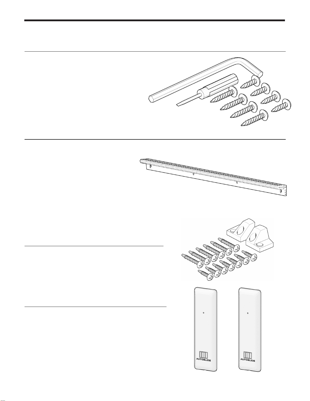
SCREWS AND TOOLS
Use the included screws to mount the
AutoSlide drive unit. The small flathead
screwdriver is used to adjust the DIP
switch positions, and the Allen key may
be used to re-hand the drive unit if
needed. Note that additional screws may
be needed depending on your door.
RACK
The track mounted to your active
sliding door panel. The motor gear
uses the rack to push and pull your
door open and closed. Each track is
20” long, and two are included with
every kit.
RACK SCREWS
Use these screws and endcaps to attach the
rack to your active sliding panel.
WALL PUSH BUTTONS
Used to activate the AutoSlide system to open
and close the door. These buttons connect
wirelessly. Two are included with every system.

5hh
WHAT YOU’LL NEED
SCREWDRIVER
A No. 2 flat head
screwdriver and
Phillips head
screwdriver are
recommended.
DRILL
The unit and tracks
will need to be drill
mounted to the door.
An assortment of drill
bits is recommended.
HACK SAW
Needed to cut off
any excess rack
once sized to the
sliding panel width.
TAPE MEASURE & MARKING PENCIL
Needed for
marking and
measuring drill
holes, rack
lengths.
MOUNTING MEDIUM RECOMMENDED FIXING METHOD
DRYWALL
DRYWALL ANCHORS
MASONRY CONCRETE ANCHORS
TAPCONS
VINYL, WOOD NORMAL SCREWS
SELF
-
TAPPER
S
METAL
DRILL PILOT HOLE &
SELF
-
TAPPERS
Depending on the door and mounting options, additional materials may be needed to
attach the system to the door. This may include shims to extend out the rack or move
the unit down, drywall anchors or concrete anchors, specialized screws, etc. For
mounting assistance, please contact Autoslide support staff directly with pictures of the
door and frame.

STAGES OF A STANDARD INSTALL INCLUDE…
Approximately
90 minutes
INSTALL
During the install, you will mount the AutoSlide
drive system to the door frame or floor, then attach
the rack to the sliding door panel.
PREPARE
To prepare for the install, you will need to
assess the scenario: check the door's readiness,
test the drag force of the door, plan how the
system will mount, and gather any necessary
tools and materials.
OPERATE
To operate your door, you will need to connect the
power and program the Controller. Once
connected, you can then synchronize the Wall
Push Buttons and/or other sensors to the Controller
and test how the door operates.
FINALIZE
Once installed and set up, place the cover back on
the drive unit and conceal cables as desired. The
unit can also be concealed and covered with a
faux valence or access panel.

7hh
BEFORE YOU BEGIN
You will need a power point (outlet)
near your door to plug in your
AutoSlide unit. Confirm a power
point is near the installation position
and can be reached by the included
power cable. Otherwise, a heavy
duty extension cable or AutoSlide
extension cable can be used.
Note: If necessary, contact a
professional electrician to install a
new outlet or electric cabling.
WORKING ORDER
Assess the operating condition of your door before installing the
AutoSlide. Check the door:
Rolls smoothly and is level. The best way to check if the
door is level is by closing the door, leaving a finger size
gap between door and jamb. Run your finger along the
gap to see if it is even from top to bottom.
Track is clean and is free of foreign objects. If
necessary, use a silicone or aluminum based lubricant
to reduce resistance.
Note: If the door is not sliding smoothly or level, contact a
local professional to perform maintenance.
Close door completely
Check if edge of door isn’t
parallel with edge of jamb

THE FRICTION TEST
If the Velcro…
Then…
Stays intact Your door is ready for the
AutoSlide system to be installed.
Go to the next page.
Breaks during
the test
Your door is not yet ready for the
AutoSlide to be installed. You
may need to improve the sliding
action with some maintenance.
Note: If the door is in good
working order but is too heavy,
you must upgrade to an Elite
Motor.
Contact Autoslide about
upgrading at (833) 337-5433.
A simple friction test is used to confirm the drag
force of your door. This will determine if the
Standard Motor or the Elite Motor is needed to
open and close your door. Your sliding door must
be in proper working condition and run freely
along its track.
1. Close the door.
2. Wrap/loop the friction tester
around the sliding door handle
and secure the Velcro.
3. Pull on the Friction Tester with even force
to fully open and close the door 3 times.
Use the same force as you would to
normally open the door and assess.
Standard Motors
will have a
silver
barrel
Elite Motors will have a black barrel
The test strip is only
used on Standard
units. If you already
have an Elite unit,
this test can be
skipped.

9hh
DRIVE MOUNTING OPTIONS - TOP
The drive system's preferred mounting location
is to the head above the door. The unit may be
mounted inside or outside and is determined by
the track of the active panel (i.e. active panel on
inside track requires mounting inside the home).
When possible, an inside mount is the preferred
location.
TOP MOUNT OVER FIXED PANEL
This is the preferred mounting option when the
sliding panel opens to the left when viewed on
the side of the active panel (as shown).
If the system must be mounted over the fixed panel (for
clearance/aesthetic purposes) and the door opens to the
right, it is necessary to rehand the unit (see Section 07
prior to installing).
ADAPTER BRACKET
If the door header doesn’t have enough depth to
mount the unit onto it, you can use the included
mounting adapter "L" bracket to facilitate a
mount directly to the wall. The bracket can be
used in a variety of ways, including as
reinforcement.
In some situations, it may be necessary to drill new holes
into the unit base. If so, take great care to not damage
any hardware or cables.
VERTICAL GAP
If the motor wheel can’t vertically meet the track
(and the track is placed as high as possible), use
a block of wood or metal to shim the unit down
closer to the track. It will likely be necessary to
mark and pre-drill your holes in the shim.
SLIDING
PANEL
SLIDING
PANEL
WALL
DOOR
ADAPTER
BRACKET
Top Mount Over Active Panel
Top Mount Over Fixed Panel
Inside vs. Outside Mount
Ce manuel convient aux modèles suivants
2
Table des matières
Autres manuels Autoslide Système d'ouverture de porte


