Auto Anchor 710-6 Manuel utilisateur

1
AutoAnchor 710-6 Owner’s Manual
Part 1 Important Information 2
Part 2 Installation 5
Part 3 Set Up 18
Part 4 Operation 35
Part 5 Maintenance 45
Part 6 Troubleshooting 46
Index
TABLE OF CONTENTS
To the best of our knowledge the information in this manual was correct at the time
of printing. However, the AutoAnchor products are continuously being reviewed and
improved and product specifications may be changed without notice. The latest product
specifications may not be reflected in this version of the manual. The documentation
relating to the AutoAnchor products is created in the English language and may be
translated from English to another language. In the event of any conflict between
translated documents, the English language version will be the official version.

2
• The AA710 should only be installed by a qualified marine electrician. Do not
attempt to install the AA710 unless you are suitably qualified.
• This manual supports the use of the AA710 only. The appropriate manufacturer’s
instructions must be followed for the installation and use of the equipment the
AA710 is set up to control.
• There must be an alternative method available to operate the windlass, thruster or
other equipment. A failure of the wireless link will result in loss of control of the
equipment via the AA710.
• The AA710 can be fitted to most vertical windlasses. A horizontal windlass may
require a sensor holder or a custom designed sensor which is not included in the
standard pack. Check with your supplier or the AutoAnchor manufacturer.
• For chain counting the AA710 must be fitted to a windlass with a dual direction
control box or solenoid pack.
• Alloy, steel or carbon fibre will restrict the wireless communication. The AA702
base station must be positioned to avoid this or an antenna can be fitted.
Contact your supplier or the AutoAnchor manufacturer for options.
• Information for installation and operation of the AA710 is supplied, including
pre-set windlass profile lists, wiring diagrams, the Owner’s Manual and
the Quick User Guide. All documents must be left on board for the owner.
• Non compliance with the instructions could impair operation of the AA710, the
windlass, thruster or other equipment and could result in personal injury and/or
damage to the boat.
• Non compliance with the instructions will negate the manufacturer’s warranty.
• The AA710 manufacturer and supplier accept no liability for personal injury or
property damage resulting from failure to follow the installation and operation
instructions or the use of the AA710 in a way that may cause accidents or
damage or that may violate the law.
• All the technical and cable specifications must be checked and adhered to and
wiring diagrams must be followed without modification.
• Before use the AA710 must be correctly set up for all the equipment it is to control
and tested in a safe environment. The AA710 will not count correctly if the
windlass selection is wrong or the windlass is not standard (eg it is installed
with a different chainwheel or motor).
• All installations must be carried out in accordance with USCG, ABYC, NMMA and
BMEA requirements.
• When this product reaches the end of its useful life it must be disposed of in
accordance with local regulations.
PART 1 IMPORTANT INFORMATION
READ BEFORE INSTALLING OR USING THE AUTOANCHOR

3
TECHNICAL SPECIFICATIONS
Parameter AA710 Remote Console AA702 Base Station
Power Supply 2 x AA 1.5V Batteries 12V/24V DC
Maximum Voltage 30V DC
Current Consumption N/A 50mA
Output Maximum
Current Draw
N/A 12V DC: 3.5A
24V DC: 3.5A
The system has internal current
limiting and thermal shutdown.
Output Minimum
Current Draw
N/A 12V DC: 10mA
24V DC: 20mA
IP Rating IP67 IP67
Operating Temperature
Range
23oF to 140oF (-5oC to 60oC) 23oF to 140oF (-5oC to 60oC)
Wireless Transmission 2.4GHz ISM Band, IEEE 802.15.4 Compliant, 64 Bit Unique ID
Wireless Range Typical Minimum 10m (30ft). Range depends on installation.
Outputs 6
System Supports Up to 3 base stations and 3 consoles
Rode - Chain Only Stainless or galvanised steel.
Rode - Rope and Chain Must have a minimum of 10ft (3m) of chain. Chain must be
galvanised steel. Rope should be a good quality, nylon anchor
rope. Type 66 or equivalent.
DC windlasses require a dual direction solenoid

4
RADIO FREQUENCY COMPLIANCE
FCC Information:
This device complies with Part 15 of the FCC Rules. Operation is subject to the following
two conditions: (1) this device may not cause harmful interference and (2) this device must
accept any interference received, including interference that may cause undesired
operation.
Modifications not expressly approved by the manufacturer could void the user’s authority to
operate this equipment.
This device generates, uses, and can radiate radio frequency energy and, if not installed
and used in accordance with the manufacturer’s instructions, may cause harmful
interference to radio communications.
ESTI Information (CE):
This device is compliant with the essential requirements of the R&TTE Directive 99/5/EC,
meeting the European harmonized EMC and low-voltage/safety standards.
ELECTROMAGNETIC COMPATIBILITY (EMC)
FCC Information:
This device complies with CFR47 Part 15 of FCC Rules for Class B equipment.
ESTI Information (CE):
This device meets the relevant standards set out in European Standard EN 60945:2002 for
maritime navigation and radio communication equipment and systems. These standards
are intended to provide reasonable protection against interference by other emission
generating products on the boat. Compliance with these standards is no guarantee that
interference will not occur in a particular installation. The installation instructions must be
followed to minimise the potential for interference.
Note: If shielded cable is not used for the sensor connections this will compromise the
EMC and may invalidate the warranty.
AA710 equipment (AA702 base station and AA710 remote console) must be installed at
least 3ft (1m) away from any equipment transmitting or cables carrying radio signals eg
VHF radios, modified sine wave inverters, cables and antennas or radar antennas; and at
least 6ft (2m) away from any SSB equipment. AA702 cables must be installed at least
1.5ft (500mm) away from such items.

5
PART 2 INSTALLATION
2.1 INSTALLATION TO OPERATE A WINDLASS
2.1.1 MAGNET AND SENSOR INSTALLATION
PLEASE READ BEFORE COMMENCING INSTALLATION
Correct magnet and sensor installation is critical for successful AutoAnchor
operation.
The AutoAnchor can be installed on vertical windlasses, drum winches and most
horizontal windlasses. Installation differs depending on the windlass type and on the
rode (all-chain or rope and chain). Please follow the instructions for your windlass
and rode. If it is not possible to comply with these instructions please check with the
AutoAnchor manufacturer or your supplier for other options or if you are not sure how to
proceed.
2.1.2 MAGNET INSTALLATION OVERVIEW
Check before starting. Your chainwheel may be prefitted with a magnet or predrilled
ready for you to fit the magnet.
Magnet Polarity: Not relevant when using the grey AA sensor (#9067) or a reed switch
sensor. If retrofitting, using the black AA sensor (#9008), the south pole (marked side) of
the magnet must face the sensor.
Magnet Seal: Insert the magnet into the hole and cover it with a minimum of 1mm of epoxy
to protect it against corrosion. See Fig 1 on page 8.
Magnet Size and Position: Refer to the instructions for your specific windlass type.
2.1.3 SENSOR INSTALLATION OVERVIEW
Vertical Windlasses: The sensor is fitted in the deckplate. Some deckplates are predrilled
for the sensor. Others have a dimple or mark to show where the sensor should be fitted.
If the windlass is not factory drilled, drill a hole 10.3mm (13/32”) diameter through the
windlass deckplate. See the instructions for your specific windlass type.
+RUL]RQWDO:LQGODVVHV6RPHWLPHVLWLVQRWSRVVLEOHWR¿WWKHVHQVRUWRDKRUL]RQWDO
ZLQGODVVRULWPD\QHHGWREH¿WWHGE\WKHZLQGODVVPDQXIDFWXUHU%HIRUHVWDUWLQJ
FKHFNZLWKWKH$XWR$QFKRUPDQXIDFWXUHURUVXSSOLHUWKDWLWLVSRVVLEOHWR¿WWKH
VHQVRUWR\RXUZLQGODVV<RXPD\QHHGDVSHFLDO¿WWLQJ
Drilling the Deck: Before drilling into the deck, ensure there is nothing below the deck
that could be damaged and that any hole you drill will not weaken the boat’s structure. Drill
a hole 10.3mm (13/32”) diameter through the deck. Ensure this hole is directly in line with
the sensor hole in the deckplate.

6
Part #9507 Male Field Connector
Part #9508 Female Field Connector
If there is no plug on the sensor cable attach the AA field
connector to the wires and use the connecting cable as above.
2.1.4 PLUG AND PLAY SENSOR CABLE
The AutoAnchor plug and play sensor cable is 2 core tinned shielded cable. It must be
used to connect the sensor to the console unit. Ensure the connectors are firmly screwed
together.
The warranty does not apply if the sensor cable plugs are removed.
The sensor cable is fitted with a female plug to connect direct to the male connector on the
AA702 base station. If a longer length is required, sensor connecting cable, with a male
plug at each end, is available in the following lengths:
6.5 m (21.33 ft) Part #9500
10 m (32.81 ft) Part #9501
15 m (49.21 ft) Part #9502
20 m (66.62 ft) Part #9503
25 m (82 ft) Part #9504
35 m (114.83 ft) Part #9514
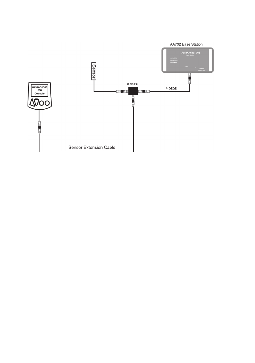
A 2m male/female cable (Part #9505) plus a gender changer (Part #9510) will be required
to connect the extension cable to the base station.
Field Connectors
Sensor Connection: The sensor is plugged direct into the AA702 base station. Do not
leave the cable hanging loose, it must be tied in place with cable ties. Extension cable,
gender changers and field connectors are available if required.
Sensor Plug
Fitting the Sensor: Do not force the sensor into the hole. Hammering the sensor head
can damage the internal electronics. Ensure the sensor head is positioned so that it will not
be hit by the chainwheel during windlass operation and that it is at least 300mm (1ft) away
from the battery and motor cables. Secure the sensor using a good quality neutral cure
silicone or a strong adhesive eg. Sikaflex 291 or 3M 5200.
Connecting 2 cables together:
If you need to extend the cable length - 2 cables can be joined
together using Part #9510 Gender Changer.
Antenna Plug
7
Dual Installation with Other AA Products
Use the T adaptor Part #9506 and the 2m Male/Female extension cable
Part #9505.
2.1.5 REED SWITCH SENSORS
Some windlasses are supplied pre-fitted with a reed switch sensor. Reed switch sensors
must have a 10mm x 8mm magnet (#9061) and the gap between the reed switch sensor
and the magnet must be a minimum of 3mm and a maximum of 5mm. This sensor requires
a field connector.
The AutoAnchor will operate with a reed switch sensor for all-chain rode. If using
combination rope and chain rode the reed switch sensor provides a reasonably accurate
count of rode deployed but on retrieval the display may be incorrect because it cannot
allow for the stretch in the rope.
For an accurate rope and chain count, the reed switch sensor should be replaced with the
AA grey sensor (#9067).
2.1.6 SENSOR TUNING
When the AutoAnchor is completely installed the sensor must be tuned. See the
instructions on page 37.

8
Magnet Fit: Drill a hole 10.3mm (13/32”) diameter and 9.5mm (3/8”) deep to fit the
magnet in the underside of a spoke in the bottom of the chainwheel. Cover the magnet
with a minimum of 1 mm epoxy. The magnet should be aligned with the sensor. See Fig 1.
2.1.7 INSTALLATION ON A VERTICAL WINDLASS - CHAIN ONLY
Magnet Size: Standard size is 10mm x 8mmm (#9061). This may be replaced with the
smaller 6mm x 4mm (#9009) magnet if required for your windlass.
Fig 1 - All sensors
Seal with minimum 1mm epoxy.
Magnet
Sensor
Gap Between the Sensor and Magnet:
Sensor Magnet Size Gap
AA Grey Sensor #9067 6mm x 4mm Minimum 3mm - Maximum 30mm
AA Grey Sensor #9067 10mm x 8mm Minimum 3mm - Maximum 50mm
AA Black Sensor #9008 All Magnets Minimum 3mm - Maximum 8mm
Reed Switch Sensor 10mm x 8mm Minimum 3mm - Maximum 5mm
Chainwheel
Deckplate
Refer to the Overview Notes on page 5 before starting installation.
Sensor Connection: Ideally the sensor should be plugged directly into the AA702 base
station. If longer cable is required use the AA 2m male/female extension cable (Part
#9505) or one of the AA standard male/male extension cables plus the 2m cable and a
gender changer. Ensure the connectors are firmly screwed together. See the information
on page 6.
Loose cable should be tied in place with cable ties and kept clear of chain.
Sensor Position: The AA black sensor and the reed switch sensor must be fitted direclty
in line with the magnet in the chainwheel. See Fig 1 above. The AA grey sensor may be
fitted up to 20mm out of alignment. The gap between the sensor and magnet must be as
per the table below.
Note: If it is not possible to
align the sensor and magnet
exactly the AA grey sensor may
be fitted up to 20mm out of
alignment. The AA black sensor
and the reed switch sensor must
be directly aligned.

9
Magnet Fit: Some windlasses are predrilled and others need a special fit. Please check
with your supplier. The usual fit is as follows: Drill a hole 10.3mm (13/32”) diameter and
9.5mm (3/8”) deep into a spoke in the top of the chainwheel. Cover the magnet with a
minimum of 1mm epoxy. The magnet and sensor must be aligned so that the anchor rode
passes between them. See Figs 2 & 3.
Sensor
Magnet
Fig 2 Fig 4
Seal with minimum 1mm epoxy.
Magnet
2.1.8 INSTALLATION ON A VERTICAL WINDLASS - ROPE & CHAIN
For an accurate rope and chain count, the rode must run between the sensor and
magnet. If your windlass is prefitted with a magnet in the bottom of the chainwheel you
need to remove it and fit a new magnet in the top of the chainwheel. Refer to Figs 2-4.
Magnet Size: 10mm X 8mm magnet (#9061). An 8mm x 6mm magnet (#9052) may be
used on smaller windlasses. Check with your supplier.
Sensor Position: The sensor must be fitted into the deckplate within the sensor position
range at the stern end of the windlass (See Fig 5). It must also be aligned with the magnet
so that the rode passes between the sensor and the magnet. The centre of the magnet
and the centre of the sensor may be up to 10mm out of direct alignment (See Fig 3). The
gap between the sensor and magnet must be as per the table below.
Chainwheel
Deckplate
Fig 3
Sensor & Magnet may be up to
10mm out of direct alignment
10mm
Sensor
Magnet
Sensor
Magnet
Fig 5
Sensor Position Rope & Chain Vertical Windlasses
Gap Between the Sensor and Magnet
Sensor Magnet Size Gap
AA Grey Sensor #9067 8mm x 6mm Minimum 30mm - Maximum 44mm
AA Grey Sensor #9067 10mm x 8mm Minimum 35mm - Maximum 50mm
Refer to the Overview Notes on page 5 before starting installation.
Sensor Connection: If longer cable is
required the AutoAnchor plug and play
sensor extension cable must be used
to connect the sensor to the AA702
base station. Ensure the connectors
are firmly screwed together. See the
information on page 6.
Loose cable should be tied in place
with cable ties and kept clear of
chain.
Sensor Position
Range
90oBow
Stern
Rode
Anchor
Locker
Chainwheel
Ce manuel convient aux modèles suivants
2
Table des matières
Autres manuels Auto Anchor Télécommande


Manuels Télécommande populaires d'autres marques

Panasonic
Panasonic EUR7622KB0 Manuel utilisateur

Bang & Olufsen
Bang & Olufsen Beo4 Manuel utilisateur

Sunwave Tech.
Sunwave Tech. RemoteComm SRC-7000 Manuel utilisateur

Multiplex
Multiplex PROFI TX 9 Manuel utilisateur

One Remote
One Remote RMB4 Manuel utilisateur

FUTABA
FUTABA 9ZAP - PART2 Manuel utilisateur


