Audi A4 - GUIDE 2008 Manuel utilisateur

Installation instructions
Audi A4/A5 (B8 series) 2008 ▶
Engine sound system
For scope of delivery 8T0.071.901*
Audi Genuine Accessories®
Edition 11/2012
Service
Service Department. Technical Information

Contents
1 General notes . . . . . . . . . . . . . . . . . . . . . . . . . . . . . . . . . . . . . . . . . . . . . . . . . . . . . . . . . . . . . . . . . . . . . . . . . . . . . . . . . . . . . . . . . . . . . . 1
2 Parts overview . . . . . . . . . . . . . . . . . . . . . . . . . . . . . . . . . . . . . . . . . . . . . . . . . . . . . . . . . . . . . . . . . . . . . . . . . . . . . . . . . . . . . . . . . . . . . 2
3 Sequence of operations . . . . . . . . . . . . . . . . . . . . . . . . . . . . . . . . . . . . . . . . . . . . . . . . . . . . . . . . . . . . . . . . . . . . . . . . . . . . . . . . . . 3
3.1 Preparations . . . . . . . . . . . . . . . . . . . . . . . . . . . . . . . . . . . . . . . . . . . . . . . . . . . . . . . . . . . . . . . . . . . . . . . . . . . . . . . . . . . . . . . . . . . . . . . . . 3
3.2 Assembly overview of the electrical connection . . . . . . . . . . . . . . . . . . . . . . . . . . . . . . . . . . . . . . . . . . . . . . . . . . . . . . . . . . 4
3.3 Mounting the control unit — connecting to the on-board supply . . . . . . . . . . . . . . . . . . . . . . . . . . . . . . . . . . . . . . . . 4
3.4 Assembly overview of the 4-cylinder TDI exhaust system . . . . . . . . . . . . . . . . . . . . . . . . . . . . . . . . . . . . . . . . . . . . . . . 8
3.5 Assembling the exhaust system: 4-cylinder TDI . . . . . . . . . . . . . . . . . . . . . . . . . . . . . . . . . . . . . . . . . . . . . . . . . . . . . . . . . . 9
3.6 Assembly overview of the 6-cylinder TDI exhaust system . . . . . . . . . . . . . . . . . . . . . . . . . . . . . . . . . . . . . . . . . . . . . . . 13
3.7 Assembling the exhaust system: 6-cylinder TDI . . . . . . . . . . . . . . . . . . . . . . . . . . . . . . . . . . . . . . . . . . . . . . . . . . . . . . . . . . 13
3.8 Final tasks . . . . . . . . . . . . . . . . . . . . . . . . . . . . . . . . . . . . . . . . . . . . . . . . . . . . . . . . . . . . . . . . . . . . . . . . . . . . . . . . . . . . . . . . . . . . . . . . . . . 16
Service
All rights reserved.
No reproduction without prior agreement from publisher.
Copyright © 2012 Audi AG, Ingolstadt Printed in Germany

1 General notes
Please read and take note of these WARNING, Caution and
Note descriptions before carrying out maintenance or repair
work.
WARNING
Text with this symbol contains information concerning
your safety and indicates potential accident and injury
risks.
Caution
Text with this symbol indicates the risk of damage to your
vehicle.
Note
Text with this symbol contains additional information.
The pages that follow contain all of the information (subject
to technical changes) needed for installation of the sound
exhaust system.
Installation of the sound exhaust system can only be per-
formed by a qualified workshop. Special tools, test equip-
ment and vehicle-specific literature will be needed to per-
form the installation. Incorrect installation can result in per-
sonal injury, damage to the vehicle or damage to other ve-
hicles.
Audi AG shall not accept responsibility in the event of fail-
ure to comply with these assembly instructions.
Installation instructions - Audi A4/A5 (B8 series) 2008 ▶
Edition 11/2012
1 General notes 1

2 Parts overview
The sound exhaust system can be retrofitted on both left
and right-hand drive vehicles.
Parts required:
Assembly set 8T0.071.901
Comprising:
Units Part number Description
1 8T0.071.905 Actuator, left
1 8T0.071.905.A Actuator, right
2 8T0.071.910 Adjustable trim panel, chrome black
6 Stainless steel pop rivet, 4 x 9.5 mm (V2A)
2 1K0.253.141.M Clamping sleeve
1 8T0.071.954 Wiring harness
1 8T0.071.953* Control unit
1 8T0.071.952 Control unit holder
1 8T0.071.956 Sound exhaust system dual nozzle
1 Installation instructions
– Check the parts to ensure they can be installed in the re-
spective vehicle!
You will also need the following for vehicles with 4-cylinder
TDI engines:
Assembly set 8T0.071.901.A
Comprising:
Units Part number Description
1 8K0.253.409.E Middle silencer, complete
1 8K0.253.144.F Mounting for middle silencer
2 N.903.484.11 Hexagon nut with washer
1 8K0.253.144.M Mounting for end silencer, right
1 1K0.253.141.M Clamping sleeve
1 N.903.484.11 Securing nut for end silencer, right
1 8F0.804.172 Heat shielding plate for Cabrio and Sportback
1 8K0 804 172 Heat shielding plate for other vehicles
4 N.907.965.02 Securing nuts for heat shielding plate
4-cylinder TDI engines require the diffuser for the dual ex-
haust system ⇒ Electronic parts catalogue.
Installation instructions - Audi A4/A5 (B8 series) 2008 ▶
Edition 11/2012
22 Parts overview

3 Sequence of operations
3.1 Preparations
– Disconnect the battery -A- ⇒ .
– Remove the right and left luggage compartment trim ⇒ Rep.
gr. 70.
– Remove the sill panel(s) from the right side of the vehicle ⇒
Rep. gr. 70.
– Remove the glove compartment ⇒ Rep. gr. 68.
– If installed, remove the control unit for the digital sound
package -J525- incl. holder ⇒ Rep. gr. 91.
Right-hand drive vehicles
– Remove the rear seat bench ⇒ Rep. gr. 72.
– Remove the centre console ⇒ Rep. gr. 68.
– Remove the dash panel cover on the driver side ⇒ Rep. gr.
68.
Installation instructions - Audi A4/A5 (B8 series) 2008 ▶
Edition 11/2012
3 Sequence of operations 3

3.2 Assembly overview of the electrical connection
1 - Electrical connection
— CAN bus
2 - Retrofit wiring har-
ness — route for left-
hand drive vehicles
3 - Retrofit wiring har-
ness — route for
right-hand drive vehi-
cles
4 - Electrical connection
— earth
q9 Nm
5 - Electrical connection
— power supply
6 - Electrical connection
— right sound activa-
tor
7 - Electrical connection
— left sound activa-
tor
8 - Control unit, sound
AGA
9 - Nut
q9 Nm
3.3 Mounting the control unit — connecting
to the on-board supply
– Centre the control unit holder on the insulation matting and
mark the drill points -1-.
– Punch mark the drill points.
– Drill the holes using a 3.0 mm drill bit (angle drill, cordless
screwdriver). Make sure that the clearance to wires and the
vehicle body is sufficient.
Caution
Do not drill into any wires!
For reasons associated with corrosion protection, use a
vacuum to continually collect the drilling chips while drill-
ing. Corrosion damage due to drilling chips is not covered
by the vehicle's warranty.
Installation instructions - Audi A4/A5 (B8 series) 2008 ▶
Edition 11/2012
43 Sequence of operations

– Drill out the holes to 5.0 mm.
– Deburr the holes thoroughly.
– Carefully remove all chips from drilling, e.g. using a work-
shop vacuum cleaner.
– In order to provide adequate protection against corrosion,
apply the following products with a brush.
◆Single-component primer filler/surfacer LGF.008.001.42/A3
◆Two-component vario filler/surfacer, grey LGF.786.004.A3
◆Audi paint to match the vehicle's colour
◆Body cavity preserving agent D.330.KD2.A1
– Position and rivet the control unit holder on the insulation
matting.
– Insert the control unit on the retrofit wiring harness, making
sure it engages.
– Screw the control unit to the holder.
– Lay the retrofit wiring harness along the standard wiring har-
ness to the relay and fuse carrier F -SF-. If the appropriate
equipment is in place, use the cable ties with clip provided to
secure the retrofit wiring harness to the rear panel.
– Lay the connector for the actuators to the corresponding
wire grommets -arrow- .
Note
The clearance for the actuators is created by mounting the ac-
tuators ⇒ “Assembling the exhaust system: 4-cylinder TDI” on
page 9 and/or ⇒ “Assembling the exhaust system: 6-cylinder
TDI” on page 13.
Installation instructions - Audi A4/A5 (B8 series) 2008 ▶
Edition 11/2012
3 Sequence of operations 5

– Loosen the fuse carrier F -SF- and unclip the fuse carrier -
E-.
– Unpin the lilac/white wire and pin it into the connector hous-
ing 1J0.972.751 provided.
– Pin the open wire end lilac/white into the vacated slot in re-
lay carrier -E-.
– Connect the two free connectors, making sure they engage.
● Up to and including model year 2011:
– Unclip fuse carrier ST4.
– Unpin the wire from the fused outgoing circuit in chamber 3
– Pin the purple/white wire from the AGA wiring harness into
the vacated chamber
– Pin the unpinned wire from the vehicle wiring harness into
the connector housing provided (1J0.972.751).
– Pin the unpinned wire from the vehicle wiring harness into
the connector housing provided (1J0.972.751) and connect
to the connector (1J0.972.762) from the AGA wiring har-
ness.
– Check for secure engagement.
– If there is no fuse in slot 3:
– Pin the purple/white wire from the AGA wiring harness into
the empty slot for fuse 3 (fuse carrier ST4).
– Insert fuse 15A (N.017.131.12) into slot 3.
– Screw the earth wire onto the earth point on the right-hand
side of the luggage compartment.
Installation instructions - Audi A4/A5 (B8 series) 2008 ▶
Edition 11/2012
63 Sequence of operations

Left-hand drive vehicles
– Lay the retrofit wiring harness on the standard wiring har-
ness along the right sill and glove compartment to the data
bus diagnostic interface -J533- -A-.
Right-hand drive vehicles
– Lay the retrofit wiring harness on the standard wiring har-
ness along the rear bench seat and centre console to the
data bus diagnostic interface -J533- -A-.
All vehicles
– Disconnect the connector -A2-.
– Open the plug.
– Unpin the orange/brown wire (slot 6) and pin into slot 2 with
the connector provided 4B0.972.623.
– Pin the orange/brown wire of the retrofit wiring harness into
the vacated slot.
– Unpin the orange/black wire (slot 16) and pin into slot 1 with
the connector provided 4B0.972.623.
– Pin the orange/black wire of the retrofit wiring harness into
the vacated slot.
– Connect the two free connectors, making sure they engage.
– Secure the retrofit wiring harness to protect against noise
and abrasion.
Note
◆The assembly should be carried out after the assembled ex-
haust system is “sound-tested”.
◆The control unit must not be coded.
Installation instructions - Audi A4/A5 (B8 series) 2008 ▶
Edition 11/2012
3 Sequence of operations 7
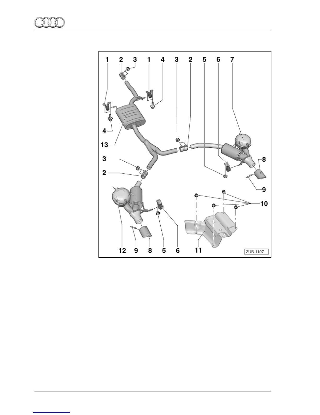
3.4 Assembly overview of the 4-cylinder TDI exhaust system
1 - Mounting
2 - Clamping sleeve
qInstall so that it is
free from tension
before tightening
the exhaust system
⇒ Rep. gr. 26
3 - Nut
q23 Nm
4 - Screw
qreplace
q20 Nm
5 - Nut
qreplace
q20 Nm
6 - Mounting
7 - Actuator
8 - Exhaust tip
q2x
qposition according
to the body version
concerned
9 - Pop rivet
q6x
10 - Nut
11 - Shield
qselect according to
the body version
concerned⇒ “Parts
overview” on page 2
qretrofit on the right side of the vehicle
12 - Actuator
13 - Silencer
qreplace
Installation instructions - Audi A4/A5 (B8 series) 2008 ▶
Edition 11/2012
83 Sequence of operations
Autres manuels pour A4 - GUIDE 2008
1
Ce manuel convient aux modèles suivants
1
Table des matières


