
atecpool SIROCCO AVHP265 Manuel utilisateur

ATECPOOL SIROCCO HEAT PUMP > User Manual
SIROCCO
INVERTER HEAT PUMP
Models: AVHP265 & AVHP308 & AVHP352& AVHP411
FULL DC INVERTER SWIMMING POOL HEAT PUMP
USER MANUAL
Please read this manual carefully before using and keep it in a safe place.

ATECPOOL SIROCCO HEAT PUMP > User Manual

ATECPOOL SIROCCO HEAT PUMP > User Manual
Contents
I. Unit Parameters .................................................................................................................. 1
1. Appearance ....................................................................................................................... 1
II. System Specification ......................................................................................................... 2
1. Specification ................................................................................................................... 2
2. Unit Dimensions .............................................................................................................. 4
3. Exploded View ................................................................................................................ 5
III. Installation Instructions ..................................................................................................... 6
1. Pre-Requirements .............................................................................................................. 6
2. Location and pipe connection............................................................................................. 6
3. Installation Layout .............................................................................................................. 7
4. Electrical Connection ......................................................................................................... 8
4.1 Wiring: .......................................................................................................................... 8
IV. Running Test .................................................................................................................... 9
1. Inspection Before Running Test ...................................................................................... 9
2. Control Function Description ........................................................................................... 9
2.1 Operation Description ................................................................................................... 9
3. Fault Code and Solution ................................................................................................ 12
3.1. Fault Code Description .............................................................................................. 12
3.2. Troubleshooting ......................................................................................................... 14
V. WIFI Settings................................................................................................................... 15

ATECPOOL SIROCCO HEAT PUMP > User Manual

ATECPOOL SIROCCO HEAT PUMP > User Manual
1
I. Unit Parameters
1. Appearance
Please read the below instructions.
● Please install the unit in compliance with local laws, regulations and standards;
● Confirm power voltage and frequency;
● The unit should be installed by a professional installer
Warning
To be installed by professional installer only
⚠

ATECPOOL SIROCCO HEAT PUMP > User Manual
2
II. System Specification
1. Specification
Model AVHP265 AVHP308
Air Temperature: 27
℃
, inlet/outlet water temperature: 26
℃
/28
℃
, humidity 80%
Heating capacity (kW) 9.2-26.5 10.3-30.8
Power input (kW) 0.62-4.34 0.7-5.06
COP 14.82-6.1 14.7-6.09
Air Temperature: 15
℃
, inlet/outlet water temperature: 26
℃
,humidity 70%
Heating capacity (kW) 7.86-17.87 8.55-19.84
Power input (kW) 1.11-3.74 1.17-4.17
COP 7.05-4.78 7.28-4.76
Air Temperature: 35
℃
, inlet/outlet water temperature: 30
℃
/28
℃
Cooling capacity (kW) 7.5-10.25 8.8-11.9
Power input (kW) 1.41-2.53 1.77-2.94
EER (W/W) 5.32-4.05 4.95-4.05
Air Temperature: 43
℃
, inlet/outlet water temperature: 30
℃
/28
℃
Cooling capacity (kW) 4.5-8.23 4.7-9.56
Power input (kW) 1.01-2.56 1.05-2.97
EER (W/W) 4.45-3.21 4.48-3.21
Power supply (V/Ph/Hz) 380-415V/3N~/50-60Hz
Max power input (kW) 6.1 6.5
Max current (A) 10.9 11.6
Heating temperature range 27°C~34°C
Cooling temperature range 26°C~15°C
Running temperature range -10°C~48°C
Refrigerant R410A
Compressor MITSUBISHI ELECTRIC ( DC inverter)
Air side heat exchanger Hydrophilic fin and tube
Water side heat exchanger Titanium tube heat exchanger
Water flow (m
³
/h) 11.4 13.2
Net dimension LxWxH (mm) 760x679x965 795*742*965
Water pipe connection (mm) 50
Net weight (kg) 105 108
Noise level dB(A) 61 62
Water proof level IPX4

ATECPOOL SIROCCO HEAT PUMP > User Manual
3
Model AVHP352 AVHP411
Air Temperature: 27
℃
, inlet/outlet water temperature: 26
℃
/28
℃
, humidity 80%
Heating capacity (kW) 11.7-35.2 12.9-41.1
Power input (kW) 0.79-5.77 0.88-6.95
COP 14.82-6.1 14.74-5.91
Air Temperature: 15
℃
, inlet/outlet water temperature: 26
℃
/28
℃
,humidity 70%
Heating capacity (kW) 8.96-24.56 9.51-28.1
Power input (kW) 1.31-5.25 1.36-5.98
COP 6.84-4.68 7-4.7
Air Temperature: 35
℃
, inlet/outlet water temperature: 30
℃
/28
℃
Cooling capacity (kW) 5.56-14.24 5.98-17.14
Power input (kW) 1.11-3.58 1.19-4.27
EER (kW) 5.01-3.98 5.03-4.01
Air Temperature: 43
℃
, inlet/outlet water temperature: 30
℃
/28
℃
Cooling capacity (kW) 5.06~11.4 5.28~13.71
Power input (kW) 1.15~3.51 1.19~4.18
EER (W/W) 4.4~3.25 4.44~3.28
Power supply (V/Ph/Hz) 380-415V/3N~/50/60Hz
Max power input (kW) 7.3 8.0
Max current (A) 13.0 14.3
Heating temperature range 27°C~34°C
Cooling temperature range 26°C~15°C
Running temperature range -10°C~48°C
Refrigerant R410A
Compressor MITSUBISHI ELECTRIC ( DC inverter)
Air side heat exchanger Hydrophilic fin and tube
Water side heat exchanger Titanium tube heat exchanger
Water flow (m
³
/h) 15.1 17.6
Net dimension LxWxH (mm) 900x812x1054
Water pipe connection (mm) 50
Net weight (kg) 137 140
Noise level dB(A) 67 68
Water proof level IPX4
The technical specification of our heat pumps is provided for information purpose only. We reserve
the right to make change without notice in advance.
1. Ambient air temperature
2. Initial water temperature
3. Noise at 1m, 4m and 10m comply with Directives EN ISO 3741 and EN ISO 354
4. Calculate according to an in-ground private swimming pool covered with bubble

ATECPOOL SIROCCO HEAT PUMP > User Manual
4
2. Unit Dimensions
Model A B C D E F G H I
AVHP265 760 679 965 725 715 375 192 155 268
AVHP308 795 742 965 760 738 430 247 155 268
AVHP352 900 812 1054 865 846 500 252 155 268
AVHP411

ATECPOOL SIROCCO HEAT PUMP > User Manual
5
3. Exploded View
1
Fan protection cover 10
Electrical box 3 19
Front panel 1
2
Fan 11
Stand column 2 20
Controller
3
Fan motor 12
Metal mesh cover 2 21
Front panel 2
4
Top cover plate 13
Fin heat exchanger 22
Fixed plate
5
Metal mesh cover 14
Four way valve welding assembly
23
Globe valve
6
Stand column 1 15
Titanium tube heat exchanger 24
Drive board
7
Damper 16
Gas liquid separator 25
Filter welding components
8
Electrical box 1 17
Inverter compressor 26
Chassis components
9
Electrical box 2 18
Stand column 3 27
Inlet piping components
ATECPOOL SIROCCO HEAT PUMP > User Manual
6
III. Installation Instructions
WARNING: Only a professional is allowed to install the heat pump. Unqualified users cannot
install by themselves, otherwise the heat pump might be damaged and the user's safety
will be risked.This section is provided for information purposes only and must be checked
and adapted if necessary, according to actual installation conditions.
1. Pre-Requirements
Equipment needed for installation of heat pump:
● Suitable power supply cable for unit’s power.
● A by-pass kit and an assembly of PVC tube, stripper, PVC adhesive and sandpaper.
● A set of wall plugs and an expansion screw.
● We recommend using a flexible PVC pipe in order to reduce transmission of vibration.
● Suitable fastening studs may be used to raise the unit.
2. Location and pipe connection
IMPORTANT: The inverter pool heat pump should be installed in a good ventilation place.
1) The frame must be fixed by bolts (M10) to a concrete base or brackets. The
concrete base must be solid and fastened; the bracket must be strong enough and
antirust treated;
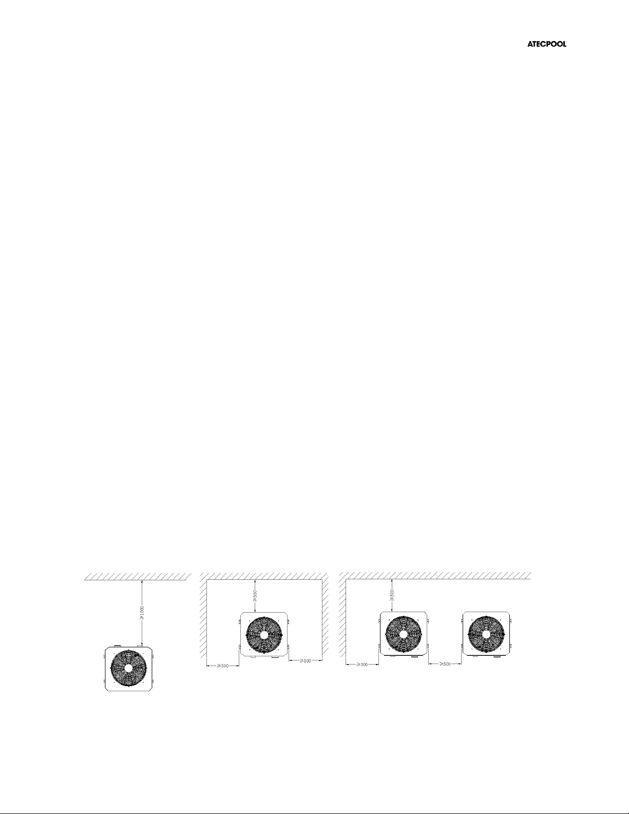
2) Please don’t stack substances that will block air flow near inlet or outlet area, make sure
there is no barrier within 50cm behind the main machine, or the efficiency of the heater will
be reduced or the machine may break;
3) The machine needs an appended pump (not included with the heat pump).
For the recommended pump specification-flux: refer to Technical Parameter,
Max. Lift ≥10m;
4) When the machine is running, there will be condensation water discharged from the
bottom, please pay attention to it. Please hold the drainage nozzle (accessory) into the
hole and clip it well, and then connect a pipe to drain the condensation water out.
Do not place anything within at least 1m in front of the heat pump. Leave at least 50cm of empty space around the sides and
rear of the heat pump. Do not put anything on or in front of the heat pump!
Ce manuel convient aux modèles suivants
3
Table des matières
Autres manuels atecpool Pompe à chaleur

atecpool
atecpool WBR-9.5H-A Manuel utilisateur

atecpool
atecpool HiHeat ATHP30 Manuel de service

atecpool
atecpool AMHP170 Manuel de service

atecpool
atecpool AMHP80 Manuel utilisateur

atecpool
atecpool AMHP110 Manuel de service

atecpool
atecpool AMHP060 Manuel utilisateur

atecpool
atecpool ATHP50 Manuel de service
Manuels Pompe à chaleur populaires d'autres marques


Mitsubishi Electric
Mitsubishi Electric PUZ-SWM60VAA Manuel utilisateur

Dimplex
Dimplex LI 16I-TUR Guide de l'utilisateur

Carrier
Carrier WSHP Open v3 Guide de configuration rapide

TGM
TGM CTV14CN018A Manuel utilisateur

Carrier
Carrier 38MGQ Series Manuel utilisateur

Kokido
Kokido K2O K880BX/EU Guide de dépannage


