ASTRO ATS-9900 Manuel utilisateur

ASTRO
ATS-9900
TABBER, LABELER,
AND STAMP AFFIXER
Operator Manual

SAFETY PRECAUTIONS
THIS EQUIPMENT PRESENTS NO PROBLEM WHEN USED PROPERLY.
OBSERVE SAFETY RULES WHEN OPERATING ATS-9900 TABBER, LABELER,
AND STAMP AFFIXER.
BEFORE USING TABBER, READ THIS MANUAL CAREFULLY AND FOLLOW
RECOMMENDED PROCEDURES, SAFETY WARNINGS, AND INSTRUCTIONS:
9 Keep hands, hair, and clothing clear of rollers and other moving parts.
9 Avoid touching moving parts or materials while machine is in use. Before clearing a jam, be sure
machine mechanisms come to a stop.
9 Always turn machine OFF before making adjustments, cleaning machine, or performing any
maintenance covered in this manual.
9 Use power cord supplied with machine. Plug it into a properly grounded, easily accessible wall
outlet located near machine. Failure to properly ground machine can result in severe personal
injury and/or fire.
9 Power cord and wall plug are primary means of disconnecting machine from power supply.
9 DO NOT use an adapter plug on line cord or wall outlet.
9 DO NOT remove ground pin from line cord.
9 DO NOT route power cord over sharp edges or trap it between furniture.
9 Avoid using wall outlets controlled by wall switches, or shared with other equipment.
9 Make sure there is no strain on power cord caused by jamming it between equipment,
walls or furniture.
9 DO NOT remove covers. Covers enclose hazardous parts that should be accessed by a qualified
service representative. Report any cover damage to your service representative.
9 This machine requires periodic maintenance. Contact your authorized service representative for
required service schedules.
9 To prevent overheating, do not cover vent openings.
9 Use this equipment only for its intended purpose.
In addition, follow any specific occupational safety and health standards for your workplace or area.
This manual is intended solely for the use and information of Astro Machine Corp. its designated
agents, customers, and their employees. The information in this guide was obtained from several
different sources that are deemed reliable by all industry standards. To the best of our
knowledge, that information is accurate in all respects. However, neither Astro Machine Corp. nor
any of its agents or employees shall be responsible for any inaccuracies contained herein.
All rights reserved. No part of this book may be reproduced or transmitted in any form or by any means, electronic or mechanical,
including photocopying, recording, or any information storage and retrieval system, without permission in writing from the publisher

TABLE OF CONTENTS
i
TABLE OF CONTENTS
SECTION 1 – Getting Acquainted 1
Front View 1
End View with Pressure Roller Cover Open 2
Control Panel 3
SECTION 2 - Assembly and Installation 4
Assembly 4
Installing Tab/Label Applicator Head 5
Installation 7
FF-14 Feeder and Feeder Base 7
SECTION 3 - Operating Tabber 9
Replacing Applicator Head 9
Loading Tabs 10
Aligning Feeder 11
Adjusting Media Guides 11
Adjusting Tab Positioning 12
Operating Tabber 13
Running a Pre-Programmed Job 15
SECTION 4 – Programming Tabber 17
Advanced Soft Key 17
Control Panel Backlight 17
Version 18
Diagnostic 18
Notes before Programming 19
Job # 19
Sensor # 20
V-Tab (Tab Sensor) Setup
20
Automatic Tab Sensor (V-Tab) Adjustment
21
Manual Tab Sensor (V-Tab) Adjustment
23
Tab Position Setup
25
Manual Tab Positioning 25
Manual Tab Positioning Features
25
Automatic Tab Positioning
28
Automatic Tab Positioning Features
28
Manual Product Length Input
30
Applying Roll Labels 31
Applying Fan-Folded Labels 31
Fan-Fold Labels Up to 2" Long 31
Fan-Folded Labels Over 2" Long 32
Applying Single Stamps 34
Applying Multiple Stamps 34
SECTION 5 – Maintenance 36
Cleaning 36
Rollers and Transport Belts 36
Cleaning Sensors 36
Lubrication 37
SECTION 6 – Troubleshooting 40
Jams 40
Tab Placement Problems 40
Diagnostics 44
APPENDIX – Specifications 47
INDEX 48

ii
NOTES
_____________________________________________________________________________________________
_____________________________________________________________________________________________
_____________________________________________________________________________________________
_____________________________________________________________________________________________
_____________________________________________________________________________________________
_____________________________________________________________________________________________
_____________________________________________________________________________________________
_____________________________________________________________________________________________
_____________________________________________________________________________________________
_____________________________________________________________________________________________
_____________________________________________________________________________________________
_____________________________________________________________________________________________
_____________________________________________________________________________________________

GETTING ACQUAINTED
1
SECTION 1 – Getting Acquainted
Front View
1
Media Skew Guide – Helps press media against Fixed Media Guide.
2
Media Guides – Help hold media on Transport Belts.
3
Take-up Reel – Winds up tab web after tab is applied.
4
Reel – Load tabs, labels or stamps on this Reel Assembly.
5
Unwind Drive Roller – Drives tab web.
6
Head Lock Thumbscrew – Locks Head Assembly in position for operating.
7
Head Fine Adjustment Knob – Used to make minute adjustments to tab or
label side-to-side position.
8
Applicator Head – Applies tab, label or stamp to media.
9
Control Panel – Control and program Tabber.
10
Media Thickness Adjustment – Operator can raise or lower Head Assembly
to adjust for thickness of media.

GETTING ACQUAINTED
2
End View with Pressure Roller Cover Open
1
Operator Side Tab Folding Guide – Folds tab under media when tabbing
from operator side of Tabber.
2
Tab Pressure Roller Lock – Locks Tab Pressure Assembly in place.
3
Applicator Head – Two Applicator Heads are supplied:
one for tabs and stamps and one for labels. (Label head shown)
4
Head and Reel Assembly – Contains Tab Reel, Tab Feed Rollers and
Take-up Reel Assemblies.
5
Transport Belts – Transport media through Tabber.
6
Safety Interlock Switches – Prevent Tabber from operating when Tab
Pressure Cover is open.
DO NOT DISABLE THESE SWITCHES AS SEVERE INJURY CAN RESULT.
7
Non-Operator Side Tab Folding Guide – Folds tab under media when
tabbing from rear of Tabber.
8
Media Forwarding Rollers – Forward media while tab is being applied.
9
Tab Pressure Rollers – Press tab to underside of media to complete seal.
10
Adjustable Media Forwarding Roller – Adjusts to forward media under
Applicator Head when applying labels or stamps.
11
Adjustable Tab Pressure Roller – Adjustable and presses label or stamp to
media to insure proper application.
GETTING ACQUAINTED
3
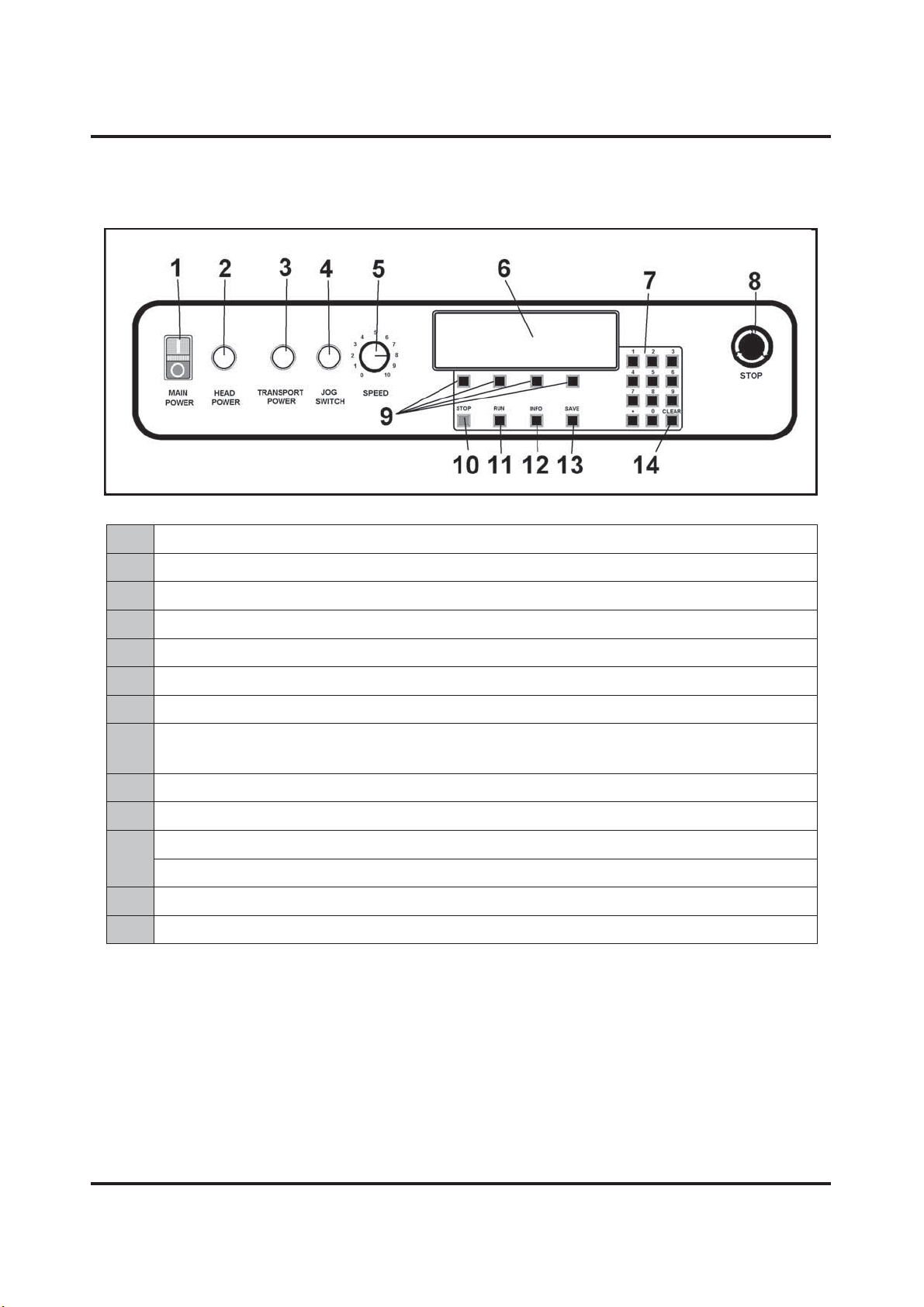
Control Panel
1
MAIN POWER SWITCH – Turns Tabber power ON and OFF.
2
HEAD POWER SWITCH – Turns power to Tab/Label motor ON.
3
TRANSPORT POWER SWITCH – Turns transport power ON and OFF.
4
JOG SWITCH – Jogs or moves transport slowly for setup purposes.
5
SPEED CONTROL – Adjusts Tabber speed.
6
LCD DISPLAY – Keeps operator informed of Tabber status.
7
KEYPAD – Used to set adjustments and program the Tabber
8
EMERGENCY STOP BUTTON – Stops Tabber. Must be turned to release it
so Tabber will start running.
9
SOFT KEYS – Used to step through various menu options to program Tabber.
10
STOP KEY – Stops Tabber and holds it in a ready state to resume operation.
11
RUN KEY – Use to start Tabber when running a job.
12
INFO KEY – Changes display to "Information Mode".
13
SAVE KEY – Used to save entries into memory.
14
CLEAR KEY – Clears any incorrect entry before it is saved in memory.

ASSEMBLY AND INSTALLATION
4
SECTION 2 - Assembly and Installation
Tabber is shipped in a single carton. Base Unit is below the Head Unit. Remove cardboard carton
from pallet, remove Head Unit from packing material. Next, remove Base Unit and place it on a
flat working surface.
Assembly
CAUTION
HEAD UNIT IS HEAVY. STRONGLY RECOMMENDED THAT
TWO TECHNICIANS INSTALL
TABBER HEAD TO BASE.
1. Place open slot of Head Unit over nylon
bushing on Base Unit. Head Unit has to be
tilted at an angle to accomplish this.
2. Lower Head into position over Head-
Adjusting Guide. There are two flats cut
into Adjusting Guide. One at top [1] and
one on left hand side [2]. Head Frame
should rest in top flat [1] and against left
hand flat [2]. When Head Assembly is
properly positioned, two screws [3] that
attach Head Assembly to Adjusting Guide
can be installed.

ASSEMBLY AND INSTALLATION
5
3. Install front mounting screw.
4. Connect two motor cables to Base Unit.
Plugs are keyed to prevent improper
insertion.
Installing Tab/Label Applicator Head
Tabber comes with two Tab/Label Applicator Heads. Narrower Head is used for tabbing and
stamp affixing. Wider Head is used for labels over 2" wide up to 4" wide and Post-it® notes.
1. Install Applicator Head by sliding it up
into cutout between Head Frame and
Head-Adjusting Guide. Attach Applicator
Head to frame using two screws [4]
supplied. Mounting holes in frame are
oval shaped. When installing Applicator
Head, hold in uppermost position when
tightening screws. Slots in frame permit
Head to be mounted in a lower position
for thin media.
2. Route cable [5] toward rear of Tabber and
plug it in. Attach main motor cable [6]
and wind and rewind motor cable [7] at
this time.

ASSEMBLY AND INSTALLATION
6
3. Install grommet [8] in slot provided in
Motor Cover.
4. Connect Reel Brake Connector to two pin
connector on top of Head Assembly.
5. Mount Reel Assembly to top of Head and
fasten it with three screws supplied.
Ce manuel convient aux modèles suivants
1
Table des matières


