aptos MAC DTU Manuel utilisateur

Version 1.0 (August 2021)

2
MACTM DTU
Contents
1. Important Safety Information..................................................................................................................................3
1.1 Read this First.........................................................................................................................................................3
1.2 Safety Instructions................................................................................................................................................ 3
1.3 User...........................................................................................................................................................................3
1.4 Support and Contact Information.................................................................................................................... 3
1.5 Other Information.................................................................................................................................................4
2. Aptos Microinverter System...............................................................................................................................4
2.1 Microinverter..........................................................................................................................................................4
2.2 DTU........................................................................................................................................................................... 4
2.3 Aptos Monitoring Server.............................................................................................................................. 4
3. Interface Layout...........................................................................................................................................................5
3.1 Interface Layout.................................................................................................................................................... 5
3.2 Export Management Function (RS485 port)...................................................................................................5
3.3 Remote Active Power Control (RS485 port).....................................................................................................6
3.4 DRM Port................................................................................................................................................................. 6
3.5 Local Install Assistant...........................................................................................................................................7
4. DTU Installation........................................................................................................................................................... 8
4.1 System Capacity.....................................................................................................................................................8
4.2 Basic Conditions Required..................................................................................................................................8
4.3 Dimensions............................................................................................................................................................. 8
4.4 System Installation Sequence............................................................................................................................9
4.5 Preparation.............................................................................................................................................................9
4.6 Install the DTU..................................................................................................................................................... 10
5. Complete Installation Map......................................................................................................................................12
6. Site Creation on HMP................................................................................................................................................13
7. Customer Login..........................................................................................................................................................14
8. Browse the Web Station...........................................................................................................................................14
9. View Phone APP......................................................................................................................................................... 15
10. LED Indicators.......................................................................................................................................................... 15
11. Technical Data..........................................................................................................................................................16
© 2021 Aptos Solar Technology, LLC. All rights reserved.

3
1. Important Safety Information
1.1 Read this First
This manual includes important instructions for installing and maintaining the Aptos Data
Transfer Unit (MACTM DTU).
1.2 Safety Instructions
Note that only professionals can install or replace DTU.
Do not try to repair DTU without approval from Aptos. If DTU is damaged, please return
to your installer for repairing/replacing. Disassembling DTU without approval from Aptos will
invalidate remaining of the warranty period.
Please read all instructions, warnings, and technical specifications carefully.
Do not use Aptos products in ways unspecified by manufacturer. Doing so may result
death/injury to persons or damage to equipment.
1.3 User
This manual is only for professional installation and maintenance personnel to use.
1.4 Support and Contact Information
Symbol
Usage
Indicates a hazardous situation that can result in deadly electric
shock hazards, other serious physical injuries, or fire hazards.
Indicates directions that must be fully understood and followed
entirely to avoid potential safety hazards including equipment
damage or personal injury.
Indicates that the described operation must not be carried out. The
reader should stop, use caution, and fully understand the operations
explained before proceeding.
© 2021 Aptos Solar Technology, LLC. All rights reserved.
MACTM DTU

4
If you have technical queries concerning our products, please contact your installer or
distributor. If further support is required, please contact Aptos’ support at this link.
www.aptossolar.com
Aptos customer service center: [email protected]m
1.5 Other Information
Product information is subject to change without notice. The user manual will be updated
frequently; please refer to Aptos Solar Technology's official website at
www.aptossolar.com for the latest version.
2. Aptos Solar Technology Microinverter System
2.1 Microinverter
The Microinverter converts the DC output of PV modules into grid-compliant AC power. It
sends the output information of PV modules and the operation data of the microinverters to
the DTU, which is the hardware basis of the module-level monitoring. With conversion
efficiency up to 96.7%and MPPT efficiency up to 99.9%, Aptos microinverters rank in
the first class of the world’s microinverter industry.
2.2 DTU
The DTU is the key component in Aptos microinverter system. It works as the
communication gateway, which operates between the Aptos microinverters and the
Aptos Monitoring Server. The DTU communicates with the microinverter wirelessly via
2.4GHz Proprietary RF (Nordic), collecting the operation data of the system. Meanwhile, the
DTU connects to the Internet via router and communicates with Aptos Monitoring Server. The
microinverter system operation data will be uploaded to Aptos Monitoring Server via DTU.
2.3 Aptos Monitoring Server
The Aptos Monitoring Server collects the operation data and status of the microinverters in
the system and provides the module-level monitoring for the users and maintenance staff.
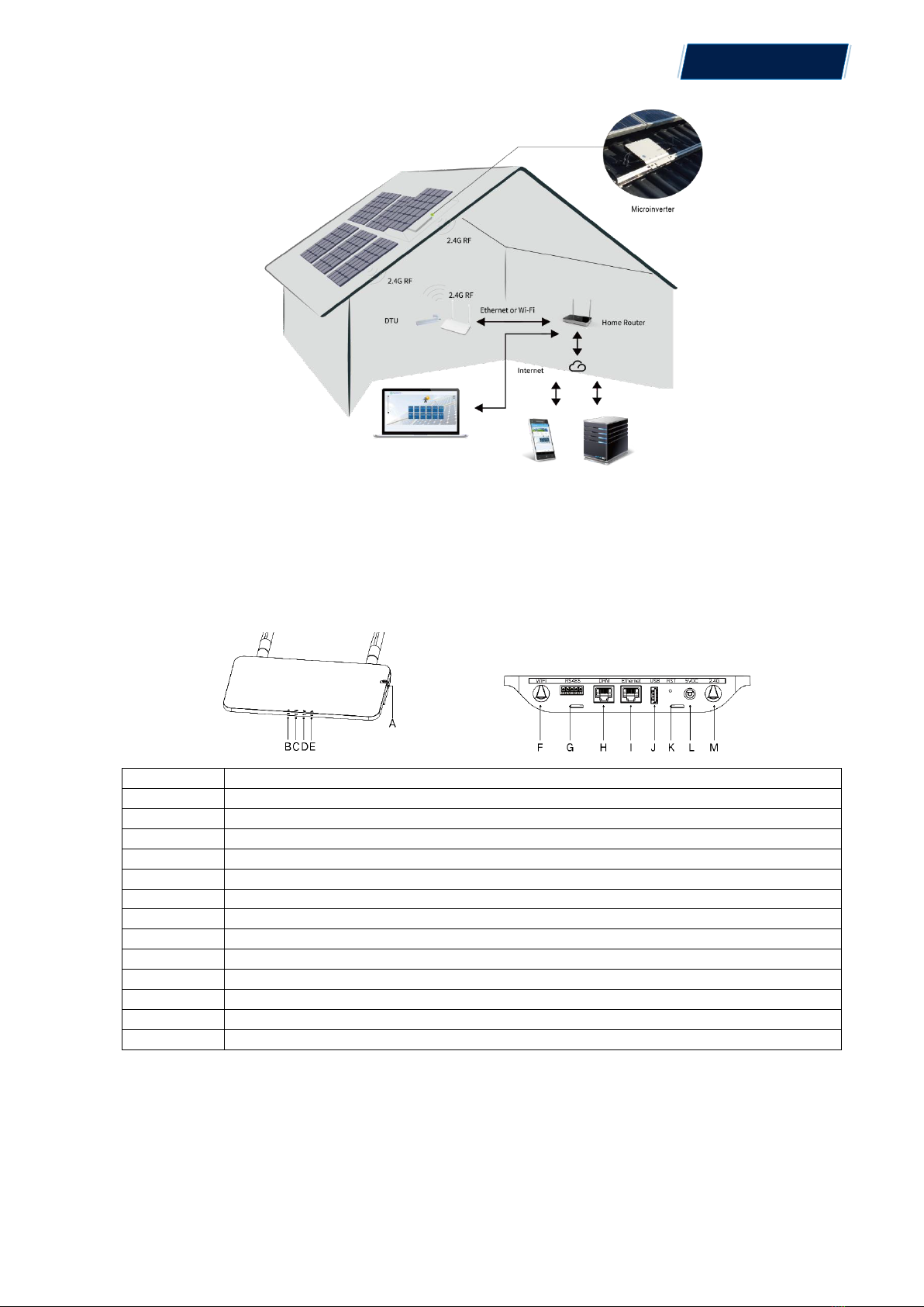
The following diagram shows the Aptos Microinverter system:
© 2021 Aptos Solar Technology, LLC. All rights reserved.
MACTM DTU

5
3. Interface Layout
3.1 Interface Layout
Item
Description
A
SD Card Slot
B
DTU Power Indicator
C
DTU Communication Indicator (With Server)
D
DTU Communication Indicator (With MI)
E
DTU Alarm Indicator
F
WiFi Antenna (2.4G)
G
RS485
H
DRM Port (For Australia only)
I
Ethernet Port
J
USB Port
K
Reset Bottom
L
Power Port
M
2.4G Antenna
3.2 Export Management Function (RS485 port)
a. Device Required.
© 2021 Aptos Solar Technology, LLC. All rights reserved.
MACTM DTU

6
Aptos Microinverter: 2-in-1 Unit and Single Unit
DTU: MACTM DTU:
Meter: Chint Meter (DDSU666)/Chint Meter (DTSU666)/CCS WattNode
Meter
b. Export Control Type.
Type 1: Zero Export: to limit the exporting power to zero so that it can prevent the
generated power feed back to the grid.
Type 2: Export Limit: to limit the exporting power within a certain value.
Type 3: Production and Consumption Monitoring: enable to measure the PV
generating under a high accuracy.
c. Installation Diagram.
MAC 800R MAC 800R
MAC 800R MAC 800R
Note: Please refer to “Aptos Export Management Technical Note” for more details.
3.3 Remote Active Power Control (RS485 port)
Some countries require generating plants to be equipped with a logic interface (input port) in
order to cease output active power or limit active power to a regulating level. This logic
input can be RS485 port, Ethernet port, etc. MACTM DTU provide RTU Modbus protocol
over RS485 port for this remote active power control. For more information, please refer to
“Modbus implementation Technical Note”.
3.4 DRM Port
DRM port is provided to support several demand response modes as below by connecting
© 2021 Aptos Solar Technology, LLC. All rights reserved.
MACTM DTU

7
external control device with a standard RJ-45 connector. For MACTM DTU, it can
support DRM0/5/6/7/8 if used with Aptos microinverters.
Mode
Requirement
DRM0
Operate the disconnection device
DRM1
Do not consume power
DRM2
Do not consume at more than 50% of rated power
DRM3
Do not consume at more than 75% of rated power AND Source reactive power if
capable
DRM4
Increase power consumption
(subject to constraints from other active DRMs)
DRM5
Do not generate power
DRM6
Do not generate at more than 50% of rated power
DRM7
Do not generate at more than 75% of rated power AND Sink reactive power if capable
DRM8
Increase power generation
(subject to constraints from other active DRMs)
3.5 Local Install Assistant
Local Install Assistant is a new function integrated with MACTM DTU. Please download
the Installer App (for installer/distributor use only) first.
MACTM DTU has improved from the previous generation of DTU products. New
functions allow installer to:
a. One step to complete the WiFi configuration;
b. Station overall Inverters status indication allows the installer to see how many MI under
this DTU is working properly (and the details for each MI) and how many is abnormal (and
the details for each MI) with one glance of eyes;
c. Add the Connection status, which will display the signal strength between each MI with
connected DTU, so that installer can adjust the DTU installation location accordingly. This
function will simplify the DTU installation, and avoid a second visit by the installler due to a
poor connection between DTU and certain MI.
Note: Please refer to “Aptos Local Install Assistant Technical Note” for more details.
© 2021 Aptos Solar Technology, LLC. All rights reserved.
MACTM DTU

8
4. DTU Installation
4.1 System Capacity
The MACTM DTU is capable of monitoring up to 99 panels. If the communication between
the DTU and microinverter caused by the installation conditions, the number of PV modules
that the DTU can monitor may be reduced.
Note: Max. monitoring quantity is for open space, installation condition meets the
requirement from both DTU and Microinverter manual, and the distance between
Microinverter and DTU needs to be within the required range.
4.2 Basic Conditions Required
Before installing the DTU, ensure that the site meets the following requirements:
Standard 220 VAC power outlet.
Stable broadband internet connection.
Router with Ethernet port.
The environmental requirements for DTU installation:
Away from dust, liquid, acidic, or corrosive gas.
The temperature should be between -20ºC and 55ºC.
If you plan to install the DTU on the wall, please prepared two #8 (4.166mm diameter) screws
and a screwdriver in advance.
4.3 Dimensions
© 2021 Aptos Solar Technology, LLC. All rights reserved.
MACTM DTU

9
1. Install the PV modules and
microinverters and repeater
2. Locate the DTU
9. Wall-mount the DTU (optional)
4. Start procedure
5. Normal operation
7. Add Microinverter ID
6. Login the local interface of the DTU
8. Check the Communication
between Microinverters and DTU
(Unit: mm)
4.4 System Installation Sequence
4.5 Preparation
A. Download the Aptos mobile App
3. Connect to the Internet
© 2021 Aptos Solar Technology, LLC. All rights reserved.
MACTM DTU

10
B. Check the box for following items:
-Aptos MACTM DTU
-Two Antennas
-Adapter
-Bracket
-5-Pin Plug
C. Choose the way MACTM DTU connects to the Internet:
Use WiFi or Ethernet. Please prepare for the following items, if
needed:
- Ethernet Cable (for Ethernet option).
-Aptos Installer App.
4.6 Install the DTU
Step 1: Install the antennas
Take two 2.4G antennas out from the box. Screw the antenna into the WiFi port and 2.4G port.
Note:If the DTU installation location is inside the metal box or under the metal / concrete roof,
extended 2.4G cable or 2.4G sucker antenna will be suggested, which can be purchased from
Aptos or local electrical store (Please contact Aptos Tech. support team for the detail type of the
Step 2: Choose an Installation Location
- Installed on the top floor to increase the signal strength.
- Installed near the center of the PV array.
© 2021 Aptos Solar Technology, LLC. All rights reserved.
MACTM DTU
Table des matières


