6
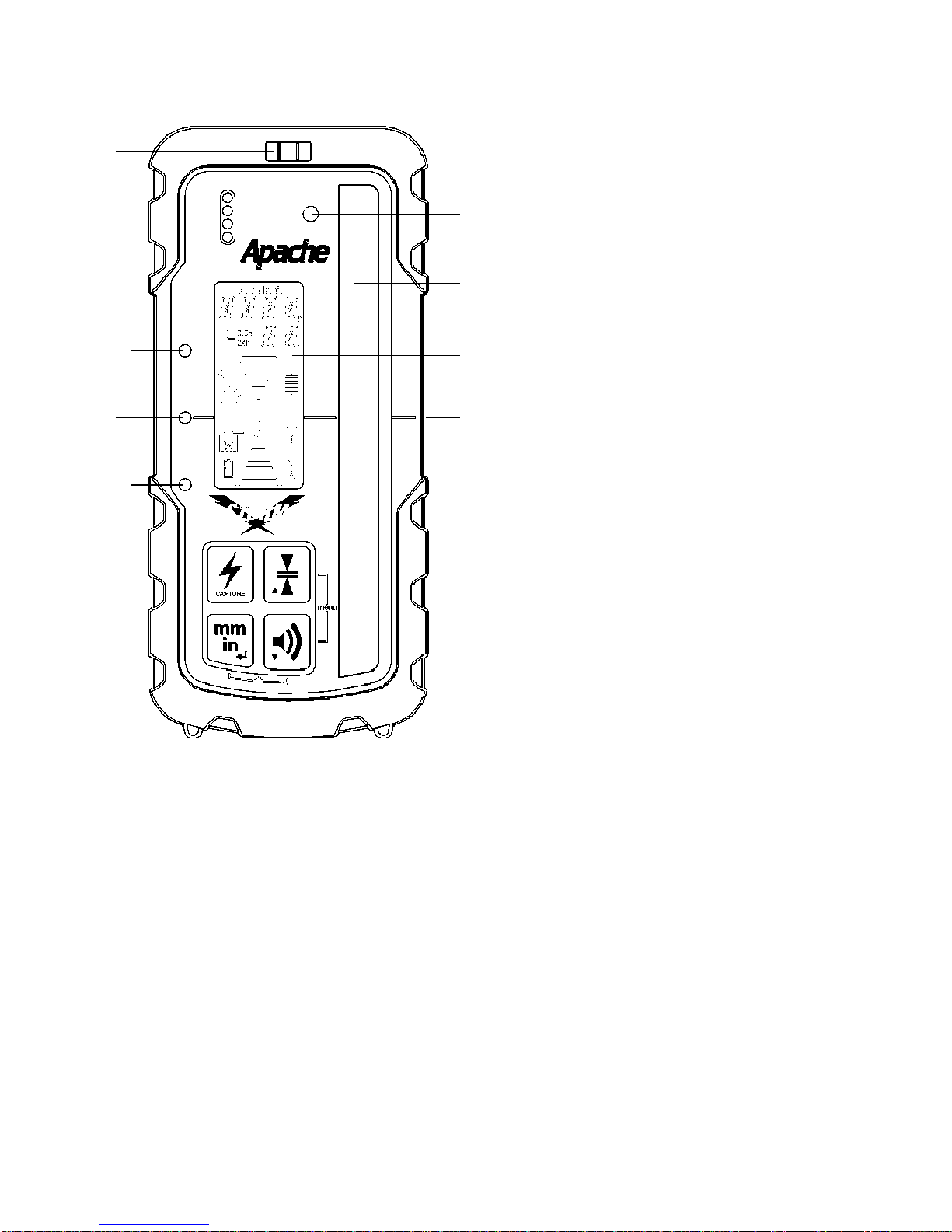
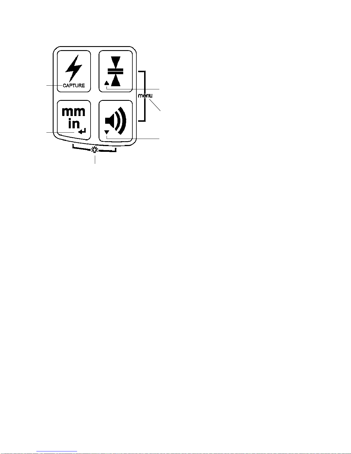
5 Operation - Primary Switch Functions
1. Power Switch - Press the
power switch to turn power
ON. All LED's, the LCD,
and the beeper will come
on momentarily. CAL will be
displayedandLED'ssequenced
as the unit goes through a
self-calibrating procedure for
approximately 3 seconds.
NOTE: Do not power up the unit in a laser beam or strobe.
If detected, the unit will revert to the previous calibration.
Press and hold the Power switch for 2 seconds to turn power OFF.
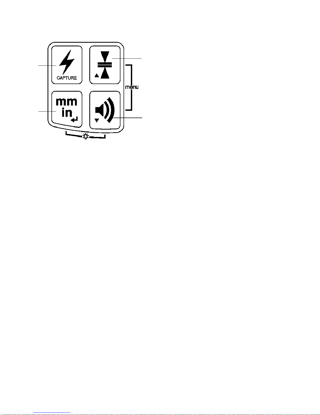
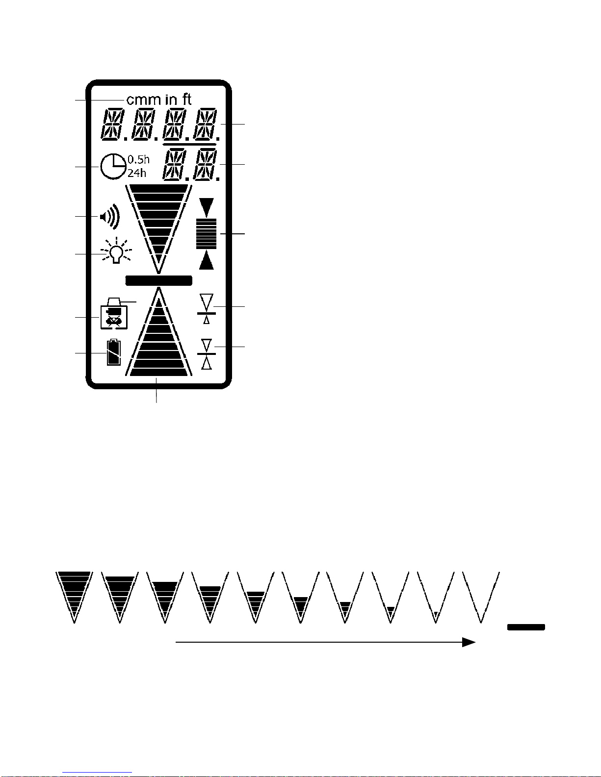
2. Units of Measure Switch - Press once to display the current
settings in the numeric display area. Press again while the
units are displayed (within one second) to change the current
selection. Subsequent presses will scroll through the setting
selections of centimeters (cm), millimeters (mm), inches (in),
fractional inches (in), and feet (ft). For fractional inches, the
fraction bar will be displayed on the LCD. The selected setting
will always be displayed on the top of the LCD.
3. Volume Switch - Pressing the switch cycles High, Medium,
Low and Off. One beep is emitted at the selected volume when
changed. When sound if Off, a single beep will signal that a laser
beam has been detected.
4. Accuracy Switch - Press once to numerically display current
accuracy settings on the LCD. Press again while the accuracy is
displayed (within one second) to change the current selection.
Subsequent presses will scroll through ve accuracy options
(Ultra Fine, Super Fine, Fine, Medium, Coarse). Refer to §11,
Specifications, for details.
4
1
23