Ames Instruments 64013 Instructions de montage

!"#"$%&'(%)*+#"$*%,$-%.$$/-00)))1.,(+&(2(*"3.$14&5
65,"7%&'(%$*4.8"4,7%#'//&($%,$-%/(&9'4$#'//&($:.,(+&(2(*"3.$14&5
Owner’s Manual & Safety Instructions
Save This Manual%Keep this manual for the safety warnings and precautions, assembly,
operating, inspection, maintenance and cleaning procedures. Write the product’s serial number in the
back of the manual near the assembly diagram (or month and year of purchase if product has no number).
Keep this manual and the receipt in a safe and dry place for future reference. 17i
When unpacking, make sure that the product is intact
and undamaged. If any parts are missing or broken,
please call 1-888-866-5797 as soon as possible.
Copyright© 2017 by Harbor Freight Tools®. All rights reserved.
No portion of this manual or any artwork contained herein may be reproduced in
any shape or form without the express written consent of Harbor Freight Tools.
Diagrams within this manual may not be drawn proportionally. Due to continuing
improvements, actual product may differ slightly from the product described herein.
Tools required for assembly and service may not be included.
;*,9%$."#%5,$*(",7%+*2&(*%'#"83%$."#%/(&9'4$1%
<,"7'(*%$&%9&%#&%4,8%(*#'7$%"8%#*("&'#%"8='(>1%
?@!6%ABC?%D@EF@G1
Page 2 <&(%$*4.8"4,7%H'*#$"&8#I%/7*,#*%4,77%JKLLLKLMMKNOPO1 Item 64013
?@<6AQ RS6;@ACRE D@CEA6E@ET6?6AFS
A,+7*%&2%T&8$*8$#
Safety ..........................................2
Specifications ..............................5
Setup ...........................................6
Operation ..................................... 8
Maintenance ...............................15
Warranty .....................................16
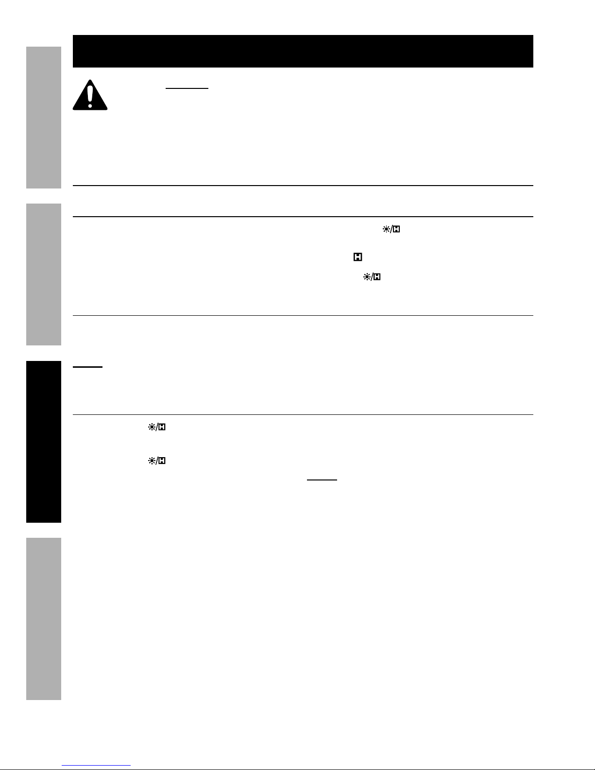
U@;ECEV%?QDWRG?%@EX%X6<CECACRE?
This is the safety alert symbol. It is used to alert you to
potential personal injury hazards. Obey all safety messages
that follow this symbol to avoid possible injury or death.
Indicates a hazardous situation which, if not avoided,
will result in death or serious injury.
Indicates a hazardous situation which, if not avoided,
could result in death or serious injury.
Indicates a hazardous situation which, if not avoided,
could result in minor or moderate injury.
Addresses practices not related to personal injury.

Page 3<&(%$*4.8"4,7%H'*#$"&8#I%/7*,#*%4,77%JKLLLKLMMKNOPO1Item 64013
?@<6AQRS6;@ACRED@CEA6E@ET6 ?6AFS
CDSR;A@EA%?@<6AQ%CE<R;D@ACRE
?,2*$>%U,(8"83#%,89%S(*4,'$"&8#
;*,9%,77%#,2*$>%),(8"83#%,89%,77%"8#$('4$"&8#1%%
Failure to follow the warnings and instructions may result
in electric shock, fire and/or serious injury.
?,Y*%,77%),(8"83#%,89%"8#$('4$"&8#%2&(%2'$'(*%(*2*(*84*1
1. Electrical shock can cause death
or injury! NEVER TOUCH exposed
conductors of electricity.
2. A*#$%4,+7*%Y&7$,3*#%)"$.%4,(*1
One use one hand when securing
the clamp around cable.
3. Inspect the Meter before use. In
addition to a general inspection,
look specifically for:
a. Pay special attention to the
insulation protecting the connectors.
b. Check the leads for exposed metal,
damaged insulation, and continuity.
c. Replace damaged test lead
immediately, before use.
4. Do not use the Meter if:
a. Either of the test leads are
damaged in any way.
b. Test leads are dirty or
have residue on them.
c. The battery is low.
d. Near any explosive
gasses or fumes.
e. Any abnormal operation is
detected.
(If in doubt about the
condition of the Meter, have
it serviced before use.)
f. The battery cover is open.
5. Power this Meter using only
the battery(ies) referenced in
the Specifications Chart.
6. Use caution when working near
voltages above 30 VAC rms, 42 VAC
peak, or 60 VDC. Voltages this high
present a risk of electric shock.
7. Disconnect the circuit’s power
before connecting the Meter in
series, when measuring current.
8. Connect the common (COM) test
lead first and disconnect it last.
9. Hold the probes with fingers
behind guards.
10. Avoid electrical shock. Use extreme
caution when working near uninsulated
conductors or bus bars. Prevent body
contact with grounded surfaces such
as pipes, radiators, ranges, and cabinet
enclosures when testing voltages.
11. Observe work area conditions. Do
not test voltages in damp or wet
locations. Don’t expose to rain.
Keep work area clean and well lit.
12. Keep children away. Children must
never be allowed in the work area.
13. Stay alert. Watch what you are doing,
use common sense. Do not operate
any Meter when you are tired.

Page 4 <&(%$*4.8"4,7%H'*#$"&8#I%/7*,#*%4,77%JKLLLKLMMKNOPO1 Item 64013
?@<6AQ RS6;@ACRE D@CEA6E@ET6?6AFS
14. Do not operate Meter if under the
influence of alcohol or drugs. Read
warning labels on prescriptions to
determine if your judgment or reflexes
are impaired while taking drugs. If there
is any doubt, do not operate the Meter.
15. People with pacemakers should
consult their physician(s) before
use. Electromagnetic fields in close
proximity to heart pacemaker could
cause pacemaker interference
or pacemaker failure.
16. Do not test voltage on circuits
higher than 600 volts.
17. Do not test current on circuits
higher than 600A.
18. Dress properly. Protective,
electrically nonconductive
clothes and nonskid footwear are
recommended when working.
19. Wear ANSI-approved safety
goggles during use.
20. Only use accessories intended
for use with this Meter.
21. Avoid damaging Meter. Use only
as specified in this manual.
22. Prior to testing resistance, diodes,
or continuity; disconnect all power
to the circuit and discharge all
high-voltage capacitors.
23. Performance of this Meter may vary
depending on battery condition.
24. Use the proper settings, terminals,
techniques, and range for the
tests performed. Start with the
range stated in the instructions.
25. Do not apply voltage to the Test
Leads when the Meter is in the
Ohms testing setting. Damage
can occur to the Meter.
26. Do not switch between testing modes
with the Meter connected to a circuit.
27. Do not use the Meter at a setting
marked as blank on the scale.
28. Have the Meter calibrated by a
qualified technician every year
to maintain accurate results.
29. Do not disassemble Meter; take
it to a qualified technician when
service or repair is required.
30. The warnings, cautions, and
instructions discussed in this
instruction manual cannot cover all
possible conditions and situations
that may occur. It must be understood
by the operator that common sense
and caution are factors which cannot
be built into this product, but must
be supplied by the operator.
%?@!6%AB6?6%CE?A;FTACRE?1

Page 5<&(%$*4.8"4,7%H'*#$"&8#I%/7*,#*%4,77%JKLLLKLMMKNOPO1Item 64013
?@<6AQRS6;@ACRED@CEA6E@ET6 ?6AFS
?/*4"2"4,$"&8#
DC Voltage Ranges: 400mV / 4V / 40V / 400V / 600V
DC Voltage Accuracy ± 0.8% of rdg + 3D
AC Voltage Ranges: 400mV / 4V / 40V / 400V / 600V
Frequency Range: 40-400Hz
AC Voltage Accuracy ± 1.0% of rdg + 5D
AC Current Ranges: 4A / 40A / 400A / 600A
Frequency Range: 50~60Hz
AC Current Accuracy ± 2.5% of rdg + 5D
Resistance Ranges: 400Ω / 4KΩ / 40KΩ / 400KΩ / 4MΩ / 40MΩ
Resistance Accuracy (@400Ω-4MΩ) ± 1.0% of rdg + 5D
(@40MΩ) ± 2.0% of rdg + 5D
Continuity Meter beeps at < 50Ω ± 20Ω
Capacitance Ranges: 5nF / 50nF / 500nF / 5μF / 50μF / 100μF
Capacitance Accuracy (@5.0nF) ± 4.0% of rdg + 5D
(@50nF-100 µF) ± 3.0% of rdg + 3D
Diode Test Forward DC Current: ~ 1mA
Reverse DC Voltage: ~ 1.5V
Frequency Range: 50Hz / 500Hz / 5kHz / 10kHz
Frequency Accuracy ± 1.0% of rdg + 5D
Duty Cycle 0.1%~99.9%
Duty Cycle Accuracy ± 2.0%
Temperature Range: -4°F to 1832°F (-20°C to 1000°C)
Temperature Accuracy ± 3.0% of rdg + 3D
Sampling Rate ~3 times/second
Operating Temperature Range: 32° - 104° F
Max Jaw Opening 28mm
Display 3-¾ digit LCD (max. display: 3999)
Battery 3x AAA batteries (included)

Page 6 <&(%$*4.8"4,7%H'*#$"&8#I%/7*,#*%4,77%JKLLLKLMMKNOPO1 Item 64013
?@<6AQ RS6;@ACRE D@CEA6E@ET6?6AFS
?*$'/%K%W*2&(*%F#*-
% ;*,9%$.*%6EAC;6%CDSR;A@EA%?@<6AQ%CE<R;D@ACRE%#*4$"&8%
,$%$.*%+*3"88"83%&2%$."#%5,8',7%"847'9"83%,77%$*Z$%'89*(%
#'+.*,9"83#%$.*(*"8%+*2&(*%#*$%'/%&(%'#*%&2%$."#%/(&9'4$1
<'84$"&8#
E&8KT&8$,4$%
!&7$,3*%
C89"4,$&(
AUTO
T'((*8$%T7,5/
;&$,(>%?)"$4.
W,4[7"3.$0X,$,%
B&79%W'$$&8
E&8KT&8$,4$%
!&7$,3*%W'$$&8
<(*H'*84>0X'$>%
T>47*%W'$$&8
X"#/7,>
C8/'$%\,4[TRD%\,4[
;,83*%W'$$&8
?*7*4$%W'$$&8
T7,5/%A("33*(
U&([7"3.$ A*#$%G*,9%T7"/

Page 7<&(%$*4.8"4,7%H'*#$"&8#I%/7*,#*%4,77%JKLLLKLMMKNOPO1Item 64013
?@<6AQRS6;@ACRED@CEA6E@ET6 ?6AFS
X"#/7,>
AUTO
?>5+&7 X*#4("/$"&8
@FAR Auto-Range
Direct Current
Alternating Current
Low Battery
]T0]< Celsius/Fahrenheit
^Percentage (duty cycle)
B_I%[B_ Hertz (frequency)
D!I%! Volts (Voltage)
μA, mA, A Amps (Current)
8<I%'<I%5< Farads (Capacitance)
Ω, kΩ, MΩ Ohms (Resistance)
Continuity
Diode
Display Hold
Page 8 <&(%$*4.8"4,7%H'*#$"&8#I%/7*,#*%4,77%JKLLLKLMMKNOPO1 Item 64013
?@<6AQ RS6;@ACRE D@CEA6E@ET6?6AFS
R/*(,$"83%C8#$('4$"&8#
% ;*,9%$.*%6EAC;6%CDSR;A@EA%?@<6AQ%CE<R;D@ACRE%#*4$"&8%
,$%$.*%+*3"88"83%&2%$."#%5,8',7%"847'9"83%,77%$*Z$%'89*(%
#'+.*,9"83#%$.*(*"8%+*2&(*%#*$%'/%&(%'#*%&2%$."#%/(&9'4$1
67*4$("4,7%#.&4[%4,8%4,'#*%9*,$.%&(%"8='(>`%E6!6;%ARFTB%
*Z/&#*9%4&89'4$&(#%&2%*7*4$("4"$>1
V*8*(,7%R/*(,$"83%C8#$('4$"&8#
X,$,%B&79
The data hold function will keep
the current reading on the Display.
To activate data hold:
1. Press the button and the
reading will be held on the Display.
The symbol appears.
2. Press again to release the hold.
D,8',7%;,83*
The Meter’s default range is @FAR. To select manual range, press ;@E. Each press
of the button increases the range. Hold the ;@E button to return to auto-range.
E&$*- Manual range cannot be used in ab@c and a@c current modes,
frequency, duty cycle, diode, continuity, or temperature modes.
W,4[7"3.$%,89%U&([7"3.$
1. Press the %button for two or more
seconds to turn on the backlight.
2. Press the %button for two or more
seconds again to turn the backlight off.
3. While in current range modes,
turning the backlight on also
turns the Clamp Worklight on.
E&$*- Frequent use of the backlight will
shorten the life of the batteries. Only
use the backlight when necessary.

Page 9<&(%$*4.8"4,7%H'*#$"&8#I%/7*,#*%4,77%JKLLLKLMMKNOPO1Item 64013
?@<6AQRS6;@ACRED@CEA6E@ET6 ?6AFS
ET!%dE&8KT&8$,4$%!&7$,3*e
1. Turn Rotary Switch to any position.
2. Hold the ET! button and move the tip
of the clamp close to the unshielded
conductor. If detected voltage is >110V
AC, Meter will beep and the Non-
Contact Voltage Indicator will flash.
U@;ECEV` 6Y*8%"2%8&%"89"4,$"&8%"#%
3"Y*8I%Y&7$,3*%5,>%#$"77%+*%/(*#*8$1
Do not rely solely on NCV detection to
determine the presence of voltage.
@'$&%S&)*(%R22
If Meter is not used for approximately 30 minutes, it will automatically turn itself off to
conserve battery power. To turn Meter back on after auto-off, press the ?6G button.

Page 10 <&(%$*4.8"4,7%H'*#$"&8#I%/7*,#*%4,77%JKLLLKLMMKNOPO1 Item 64013
?@<6AQ RS6;@ACRE D@CEA6E@ET6?6AFS
D*,#'(*5*8$%R/*(,$"&8
E&$*- Remove plugs from
ends of Test Leads (included)
before connecting to Meter.
E&$*- Test Lead probes have removable
covers for overvoltage protection. With
covers in place, Test Leads are rated for
use with CAT III circuits. Exposed probes
are rated for use with CAT II circuits.
E&$*- Insert Test Lead into Test Lead Clip
to allow for easier two hand operation.
T'((*8$%D*,#'(*5*8$
Measure AC conductors carrying
up to 600 amperes.
U@;ECEV` To avoid electric shock,
use only one hand to hold Meter
when measuring current.
U@;ECEV` Remove Test Leads
before taking measurements
with the Current Clamp.
E&$*- Amperage is always tested
in series with circuit under test.
E&$*- To measure 2- and 3-wire power
cords, use an AC Line Splitter (not included)
and follow its instructions.
1. Turn Rotary Switch to abbKMbb@c,
ab@c or a@c position. Start with
highest range if amperage is unknown.
2. Using one hand, press Trigger to
open Clamp jaws. Position Clamp
jaws around conductor to be tested.
V'"9* V'"9*
3. Center conductor between guides
in Clamp Jaws, as shown.
4. Read measured current on the Display.
Switch to lower ranges, as necessary,
to get the most accurate reading.
5. When testing is complete, turn
Rotary Switch to R<<I%and store Meter.
Table des matières
Autres manuels Ames Instruments Instrument de mesure


Manuels Instrument de mesure populaires d'autres marques


Endress+Hauser
Endress+Hauser Proline Promag 50 Caractéristiques techniques

Siemens
Siemens SITRANS F Coriolis FCT030 Manuel de la liste des pièces

KLINGER
KLINGER CMF V Series Manuel utilisateur

EXFO
EXFO FTB-2 Manuel d'exploitation et d'entretien

Keysight
Keysight M8290A Manuel utilisateur

ADTEK
ADTEK MW-5 Manuel utilisateur