AEMC PEL 102 Manuel utilisateur

Power Energy Logger
Model PEL 102 & PEL 103
CHAUVIN ARNOUX GROUP
®
ENGLISH
User Manual
www.aemc.com

Copyright © Chauvin Arnoux®, Inc. d.b.a. AEMC®Instruments. All rights reserved.
No part of this documentation may be reproduced in any form or by any means (including electronic storage and retrieval or translation into any other
language) without prior agreement and written consent from Chauvin Arnoux®, Inc., as governed by United States and International copyright laws.
Chauvin Arnoux®, Inc. d.b.a. AEMC®Instruments
15 Faraday Drive • Dover, NH 03820 USA
Tel: (800) 945-2362 or (603) 749-6434 • Fax: (603) 742-2346
This documentation is provided “as is,” without warranty of any kind, express, implied, or otherwise. Chauvin Arnoux®, Inc. has made every reasonable
effort to ensure that this documentation is accurate; but does not warrant the accuracy or completeness of the text, graphics, or other information con-
tained in this documentation. Chauvin Arnoux®, Inc. shall not be liable for any damages, special, indirect, incidental, or inconsequential; including (but
not limited to) physical, emotional or monetary damages due to lost revenues or lost profits that may result from the use of this documentation, whether
or not the user of the documentation has been advised of the possibility of such damages.
Chauvin Arnoux®, Inc, AEMC®, DataView®, AmpFlex®, MiniFlex®and PowerPad®are registered trademarks of AEMC®Instruments.
Thank you for purchasing a Power Energy Logger Model PEL 102 or PEL 103
For best results from your instrument and for your safety, read the enclosed operating instructions carefully and comply
with the precautions for use. These products must be only used by qualified and trained users.
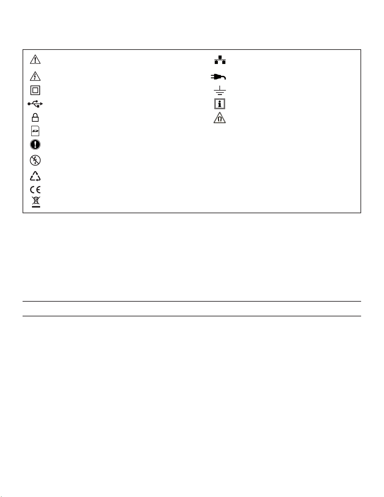
WARNING, risk of DANGER! The operator must refer to
these instructions whenever this danger symbol appears. Ethernet socket (RJ45).
CAUTION! Risk of electric shock. The voltage at the
parts marked with this symbol may be dangerous. Main power supply input.
Equipment is protected by double insulation. Ground/Earth.
USB socket. Useful information or hint to read.
SD Card. Magnetic fields can damage hard drives and
medical devices.
Kensington anti-theft system.
Important instructions to read and to fully understand.
Must not be applied to or removed from bare conductors carrying dangerous voltages.
Type B current sensor as per EN 61010-2-032.
The product has been declared recyclable after analysis of its life cycle in accordance with the ISO14040 standard.
The CE marking guarantees conformity with European directives and with regulations covering EMC.
The trash can with a line through it means that in the European Union, the product must undergo selective disposal for the
recycling of electric and electronic material, in compliance with Directive WEEE 2002/96/EC.
Definition of Measurement Categories (CAT)
■CAT IV Measurement category IV corresponds to measurements taken at the source of low-voltage installations.
Example: power feeders, counters and protection devices.
■CAT III Measurement category III corresponds to measurements on building installations.
Example: distribution panel, circuit-breakers, machines or fixed industrial devices.
■CAT II Measurement category II corresponds to measurements taken on circuits directly connected to low-voltage installations.
Example: power supply to domestic electrical appliances and portable tools.
PRECAUTIONS FOR USE
This instrument complies with safety standard IEC 61010-2-030, the leads comply with IEC 61010-031 for voltages of 1000V in
measurement category III or 600V in measurement category IV and the current sensors comply with IEC 61010-2-032. Failure to observe
the safety instructions may result in electric shock, fire, explosion, and destruction of the instrument and of the installations.
■The operator and/or the responsible authority must carefully read and clearly understand the various precautions to be taken
in use. Sound knowledge and a keen awareness of electrical hazards are essential when using this instrument.
■For your safety, use only the compatible leads and accessories delivered with the instrument, which comply with IEC
standard 61010-031 (2002). When sensors or accessories having a lower voltage rating and/or category are connected to the
instrument, the lower voltage and/or category applies to the system so constituted.
■Before each use, check that the leads, enclosures, and accessories are in perfect condition. Any lead, sensor or accessory
on which the insulation is damaged (even partially) must be repaired or scrapped.
■Do not use the instrument on networks for which the voltage or category exceeds those mentioned.
■Do not use the instrument if it seems to be damaged, incomplete, or poorly closed.
■Use only the AC power adapter and battery pack supplied by the manufacturer, which include specific safety features.
■When removing and replacing the battery and/or the SD-Card, make sure that the device is disconnected and switched off.
■We recommend using Personal Protection Equipment where required.
■Keep your hands away from unused terminals.
■If the instrument is wet, dry it before connecting it.
■All troubleshooting and metrological checks must be performed by authorized (competent and accredited) personnel, with
the instrument completely disconnected.

2
Power & Energy Logger Model PEL 102 and PEL 103
TABLE OF CONTENTS
1. INTRODUCTION .............................................................................................................. 6
1.1 Receiving Your Shipment ........................................................................................................................................6
1.2 Ordering Information ...............................................................................................................................................6
1.2.1 Accessories..................................................................................................................................................7
1.2.2 Replacement Parts.......................................................................................................................................7
2. PRODUCT FEATURES ..................................................................................................... 8
2.1 Description ..............................................................................................................................................................8
2.2 Front Panel Features ...............................................................................................................................................9
2.3 Back Panel Features .............................................................................................................................................10
2.4 Lead Inputs ...........................................................................................................................................................10
2.5 Installation of the Color-coded ID Markers ...........................................................................................................11
2.6 Connection Features.............................................................................................................................................11
2.7 Mounting and Location .........................................................................................................................................12
2.8 Theft Security ........................................................................................................................................................12
2.9 Button Functions...................................................................................................................................................12
2.10 LCD Display (PEL 103)........................................................................................................................................13
2.11 LED Status ..........................................................................................................................................................14
2.12 Memory Capacity ................................................................................................................................................15
3. OPERATION................................................................................................................... 16
3.1 Charging the Battery .............................................................................................................................................16
3.2 Operating the PEL.................................................................................................................................................16
3.3 Turning the Instrument ON/OFF ............................................................................................................................17
3.3.1 Turning the PEL ON ...................................................................................................................................17
3.3.2 Turning the PEL OFF..................................................................................................................................17
3.4 Starting/Stopping a Recording and Enabling Bluetooth.......................................................................................18
3.5 Connections ..........................................................................................................................................................18
3.5.1 Power Supply.............................................................................................................................................18
3.5.2 Standby Mode (and Display Brightness)....................................................................................................19
3.5.3 Memory Card (SD-Card) ............................................................................................................................19
3.5.4 USB Connection to the PEL ......................................................................................................................19
3.5.5 LAN Ethernet Connection to the PEL ........................................................................................................19
3.5.6 Bluetooth Connection to the PEL ..............................................................................................................20
3.5.6.1 Pairing using Windows Vista/Windows 7...........................................................................................20
3.6 Distribution Systems and PEL Hook-ups..............................................................................................................22
3.6.1 Single Phase 2-Wire ................................................................................................................................22
3.6.2 Single Phase 3-Wire (Split Phase from a center tap transformer) ............................................................22
3.6.3 3-Phase 3-Wire Power Networks ..............................................................................................................23
3.6.3.1 3-Phase 3-Wire ∆ (with 2 current sensors).........................................................................................23
3.6.3.2 3-Phase 3-Wire ∆ (with 3 current sensors).........................................................................................23
3.6.3.3 3-Phase 3-Wire Open ∆ (with 2 current sensors)...............................................................................24
3.6.3.4 3-Phase 3-Wire Open ∆ (with 3 current sensors]...............................................................................24

Power & Energy Logger Model PEL 102 and PEL 103
3
3.6.3.5 3-Phase 3-Wire Y (with 2 current sensors) ........................................................................................25
3.6.3.6 3-Phase 3-Wire Y (with 3 current sensors] ........................................................................................25
3.6.3.7 3-Phase 3-Wire ∆Balanced (with 1 current sensor) ..........................................................................26
3.6.4 3-Phase 4-Wire Y Power Networks ...........................................................................................................26
3.6.4.1 3-Phase 4-Wire Y (with 3 current sensors) ........................................................................................26
3.6.4.2 3-Phase 4-Wire Y Balanced...............................................................................................................27
3.6.4.3 3-Phase 4-Wire Y 2½ Element...........................................................................................................27
3.6.5 3-Phase 4-Wire ∆.......................................................................................................................................28
3.6.5.1 3-Phase 4-Wire ∆...............................................................................................................................28
3.6.5.2 3-Phase 4-Wire Open ∆.....................................................................................................................28
3.6.6 DC Power Networks ..................................................................................................................................29
3.6.6.1 DC 2-Wire ..........................................................................................................................................29
3.6.6.2 DC 3-Wire ..........................................................................................................................................29
3.6.6.3 DC 4-Wire ..........................................................................................................................................30
3.7 LCD Display Modes (PEL 103 Only)......................................................................................................................31
3.7.1 Base Measurements - Displayed Values...................................................................................................31
3.7.2 Energy - Displayed Values....................................................................................................................................... 34
3.7.3 Harmonic Display Values ......................................................................................................................................... 37
3.7.4 Max Display Values................................................................................................................................................... 38
3.7.5 Information Display Values ...................................................................................................................................... 39
3.7.6 Conguration (PEL 103) .............................................................................................................................40
4. PEL CONTROL PANEL - DATAVIEW®SOFTWARE .......................................................... 42
4.1 Installing DataView ................................................................................................................................................42
4.2 Connecting to a PEL .............................................................................................................................................48
4.2.1 Add an Instrument Wizard .........................................................................................................................49
4.2.2 USB Connection ........................................................................................................................................50
4.2.3 Ethernet Network Connection....................................................................................................................52
4.2.4 Bluetooth Connection ................................................................................................................................53
4.3 PEL Control Panel .................................................................................................................................................54
4.3.1 Opening and Using the Control Panel .......................................................................................................54
4.3.2 Modifying a Connection Type ....................................................................................................................57
4.3.3 Reconnecting and Disconnecting an Instrument.......................................................................................57
4.3.4 Removing an Instrument from the PEL Network .......................................................................................57
4.4 Conguring the PEL ..............................................................................................................................................58
4.4.1 General Options .........................................................................................................................................59
4.4.2 Communication Options ............................................................................................................................60
4.4.3 Measurement Tab Options.........................................................................................................................62
4.4.4 Current Sensors and Ratios.......................................................................................................................63
4.4.5 Recording Tab Options ..............................................................................................................................65
4.4.6 Meters Tab Options....................................................................................................................................67
4.4.7 Conguring and Recording Data Example ................................................................................................68
4.4.8 Modifying an Instrument’s Conguration ...................................................................................................69
4.5 Downloading Recorded Data ................................................................................................................................69
4.6 Using the Download Folder...................................................................................................................................71

4
Power & Energy Logger Model PEL 102 and PEL 103
4.7 PEL Reports ..........................................................................................................................................................72
4.7.1 Specifying the Default Report Template ....................................................................................................72
4.8 Power & Energy Logger (PEL) Android App..........................................................................................................72
5. SPECIFICATIONS ......................................................................................................... 74
5.1 Reference Conditions............................................................................................................................................74
5.2 Electrical Specications ........................................................................................................................................74
5.2.1 Voltage Inputs ............................................................................................................................................74
5.2.2 Current Inputs ............................................................................................................................................74
5.2.3 Accuracy Specications (excluding current sensors) ................................................................................75
5.2.3.1 Specications at 50/60Hz .................................................................................................................75
5.2.3.2 Specications @ 400Hz .....................................................................................................................77
5.2.3.3 Specications @ DC...........................................................................................................................77
5.2.3.4 Temperature .......................................................................................................................................78
5.2.3.5 Common Mode Rejection ..................................................................................................................78
5.2.3.6 Magnetic Field Inuence....................................................................................................................78
5.2.4 Current Sensors .........................................................................................................................................78
5.2.4.1 Precautions for Use ...........................................................................................................................78
5.2.4.2 Use and Characteristics.....................................................................................................................78
5.2.4.3 MiniFlex® MA193................................................................................................................................79
5.2.4.4 Other Current Sensors .......................................................................................................................79
5.2.4.5 Accuracy ............................................................................................................................................81
5.3 Bluetooth...............................................................................................................................................................83
5.4 Power Supply ........................................................................................................................................................83
5.5 Mechanical Specifications ....................................................................................................................................84
5.6 Environmental Specications................................................................................................................................84
5.7 Safety Specications.............................................................................................................................................84
5.8 Electromagnetic Compatibility ..............................................................................................................................84
6. MAINTENANCE ............................................................................................................. 85
6.1 Battery...................................................................................................................................................................85
6.2 Battery Indicator....................................................................................................................................................85
6.3 Cleaning ................................................................................................................................................................85
APPENDIX A...................................................................................................................... 86
A.1 Measurements ......................................................................................................................................................86
A.1.1 Definition....................................................................................................................................................86
A.1.2 Sampling....................................................................................................................................................86
A.1.2.1 Sampling Period ................................................................................................................................86
A.1.2.2 Locking of Sampling Frequency........................................................................................................87
A.1.2.3 AC/DC................................................................................................................................................87
A.1.2.4 Measurement of Neutral Current .......................................................................................................87
A.1.2.5 “1 second” Quantities........................................................................................................................87
A.1.2.6 Aggregation .......................................................................................................................................87
A.1.2.7 Max....................................................................................................................................................87
A.1.2.8 Energy Calculations...........................................................................................................................88

Power & Energy Logger Model PEL 102 and PEL 103
5
A.2 Measurement Formulas ........................................................................................................................................88
A.3 Aggregation...........................................................................................................................................................89
A.4 Supported Electrical Networks .............................................................................................................................91
A.5 Phase Order ..........................................................................................................................................................93
A.5.1 A.5.1 Current Phase Order ........................................................................................................................93
A.5.2 Voltage Phase Order..................................................................................................................................94
A.5.3 Current vs Voltage Phase Order ................................................................................................................95
A.6 Quantities According to the Supply Systems .......................................................................................................96
A.7 GLOSSARY OF TERMS ........................................................................................................................................98
Repair and Calibration.................................................................................................... 101
Technical and Sales Assistance...................................................................................... 101
Limited Warranty ............................................................................................................ 102
Warranty Repairs ............................................................................................................ 102

6
Power & Energy Logger Model PEL 102 and PEL 103
1. INTRODUCTION
1.1 Receiving Your Shipment
Upon receiving your shipment, make sure that the contents are consistent with the packing list. Notify your distributor of any
missing items. If the equipment appears to be damaged, file a claim immediately with the carrier and notify your distributor
at once, giving a detailed description of any damage. Save the damaged packing container to substantiate your claim.
1.2 Ordering Information
Power & Energy Logger Model PEL 102 (no LCD, w/3 MA193-10-BK sensors) ............................................ Cat. #2137.51
Power & Energy Logger Model PEL 103 (with LCD, w/3 MA193-10-BK sensors).......................................... Cat. #2137.52
Power & Energy Logger Model PEL 102 (no LCD, no sensors) ...................................................................... Cat. #2137.61
Power & Energy Logger Model PEL 103 (with LCD, no sensors).................................................................... Cat. #2137.62
Shipping Contents:
(1) of the following:
Power Energy Logger Model PEL 102
Power Energy Logger Model PEL 103
Cat. #2137.51 or Cat. #2137.52
OR
(3) MiniFlex®MA193-10-BK
Cat. #2140.48
(included only with
the purchase of
Cat. #2137.51 or Cat. #2137.52)
Also Included:
(1) Safety Sheet for the PEL
(1) Safety Sheet for the MiniFlex®Sensors
(1) Compliance Sheet
(1) 2 GB SD-Card
(1) Quick Start User Guide
(1) 4 GB USB Stick with User Manual & DataView®Software
(1) Battery (NiMH AAA 8.4V) - Cat.#2137.75
(1) Small Classic Tool Bag
Cat. #2133.72
(4) Black Test Leads and Alligator Clips
Cat. #2137.76
(12) Color-coded ID Markers
Cat. #2140.45
(1) 5 ft USB Cable
Cat. #2140.46
(1) Multix (mounting system)
Cat. #5000.44
(1) USB SD-Card Adapter
Cat. #5000.45
(1) Power Cord, 5 ft 115V
Cat. #5000.14

Power & Energy Logger Model PEL 102 and PEL 103
7
1.2.1 Accessories
USB cable, A/B 10 ft (3m) ................................................................................................................................Cat. #2136.80
PEL Power Adapter ..........................................................................................................................................Cat. #2137.77
AC/DC Current Probe Model J93.....................................................................................................................Cat. #2140.49
AC/DC Current Probe Model MR193-BK.........................................................................................................Cat. #2140.28
AC Current Probe Model MN93-BK.................................................................................................................Cat. #2140.32
AC Current Probe Model SR193-BK................................................................................................................Cat. #2140.33
AmpFlex® Sensor 24" Model 193-24-BK (black connector) ...........................................................................Cat. #2140.34
AmpFlex® Sensor 36" Model 193-36-BK (black connector) ...........................................................................Cat. #2140.35
AC Current Probe Model MN193-BK (black connector) ................................................................................Cat. #2140.36
MiniFlex® Current Sensor 10" Model MA193-10-BK (black connector)...........................................................Cat. #2140.48
AC/DC Current Probe Model SL261* ...............................................................................................................Cat. #1201.51
*BNC Adapter for Current Probe Model SL261..........................................................................................Cat. #2140.40
Anti-theft Kensington Laptop Security Cable (available in most ofce supply stores) .....................................................N/A
1.2.2 Replacement Parts
Small Classic Tool Bag .....................................................................................................................................Cat. #2133.72
Battery (custom factory replacement NiMH AAA 8.4V) ...................................................................................Cat. #2137.75
Lead, Set of 4, 10 ft 4mm Straight Banana Plugs with Set of Alligator Clips (Black) UL
and a Set of 12 Color-coded Input ID Markers ................................................................................................Cat. #2137.76
Set of 12 Color-coded Input ID Markers ..........................................................................................................Cat. #2140.45
USB Cable A/B, 5 ft (1.5m)...............................................................................................................................Cat. #2140.46
Power Cord, 5 ft (1.5m) 115V ...........................................................................................................................Cat. #5000.14
MultiFix (universal mounting system) ...............................................................................................................Cat. #5000.44
USB SD-card Adapter......................................................................................................................................Cat. #5000.45
DataView®Software Updates are Available at www.aemc.com
PEL Android App Available on the Google Play Store at
https://play.google.com/store/apps/details?id=com.aemc.pel&hl=en

8
Power & Energy Logger Model PEL 102 and PEL 103
2. PRODUCT FEATURES
2.1 Description
PEL: Power and Energy Logger
The PEL 102 and PEL 103 are simple-to-use, single, dual (split-phase) and three phase (Y, ∆) power and energy loggers.
The PEL offers all the necessary functions for Power/Energy data logging for most of the 50Hz, 60Hz, and 400Hz and DC
distribution systems worldwide offering numerous distribution set-ups. The PEL is designed to work in 1000V CAT III and
600V CAT IV environments.
The PEL is compact in size and fits in many distribution panels.
The PEL provides the following measurements (or calculations):
■Direct voltage measurements up to 1000V CAT III and 600V CAT IV
■AC current measurements from 200mA up to 10,000A with MA193 external current sensors
■Power measurements: VA, W and var
■Energy measurements: VAh, Wh (source, load) and varh (4 quadrants)
■Power Factor (PF), Cos ϕ, and Tan Φ
■Crest Factor
■Total Harmonic Distortion (THD) for voltages and currents
■Harmonics from the fundamental signal up to the 50th order for 50/60Hz voltages and currents
■Frequency measurements
■RMS and DC measurements @ 128 samples/cycle – each phase simultaneously
■Bright triple LCD on the Model PEL 103 (3 phases shown simultaneously)
■Storage of measured and calculated values on a SD-Card or SDHC-Card
■Automatic recognition of the different types of current sensors
■Configuration of current and voltage ratios with external sensors
■17 types of supported hook-ups or electrical distribution systems
■USB, LAN, and Bluetooth communication
■DataView® Software for data download, viewing of measurements, real-time communication with a PC and
report generation with predefined or custom templates
Autres manuels pour PEL 102
4
Ce manuel convient aux modèles suivants
1
Table des matières
Autres manuels AEMC Enregistreur de données

AEMC
AEMC Simple Logger II Guide de configuration

AEMC
AEMC DL-1080 Manuel utilisateur

AEMC
AEMC L100 Manuel utilisateur

AEMC
AEMC PEL 105 Manuel utilisateur

AEMC
AEMC L452 Manuel utilisateur

AEMC
AEMC Simple Logger II Manuel utilisateur

AEMC
AEMC L452 Manuel utilisateur

AEMC
AEMC Simple Logger II Manuel utilisateur

AEMC
AEMC Simple Logger II Series Manuel utilisateur

AEMC
AEMC PEL 52 Manuel utilisateur


