Abatron BDI2000 Manuel utilisateur

bdiNDI
JTAG debug interface for EDGE Debugger
PowerPC 4xx
User Manual
Manual Version 1.06 for BDI2000
© 1992-2008 ABATRON AG

bdiNDIJTAG debug interface for EDGE Debugger, BDI2000 (PPC4xx) User Manual 2
© Copyright 1992-2008 by ABATRON AG V 1.06
1 Introduction ................................................................................................................................. 3
1.1 BDI2000................................................................................................................................. 3
2 Installation ................................................................................................................................... 4
2.1 Connecting the BDI2000 to Target ........................................................................................ 4
2.1.1 Changing Target Processor Type ................................................................................ 6
2.2 Connecting the BDI2000 to Power Supply ............................................................................ 7
2.3 Status LED «MODE»............................................................................................................. 8
2.4 Connecting the BDI2000 to the Host ..................................................................................... 9
2.4.1 Serial line communication ............................................................................................ 9
2.4.2 Ethernet communication ............................................................................................ 10
2.5 Installation of the Configuration Software............................................................................ 11
2.6 Configuration ....................................................................................................................... 12
2.6.1 BDI2000 Setup/Update .............................................................................................. 12
3 Init List........................................................................................................................................ 14
4 BDI working modes................................................................................................................... 16
4.1 Startup Mode ....................................................................................................................... 17
4.1.1 Startup mode RESET................................................................................................. 17
4.1.2 Startup Mode STOP................................................................................................... 17
4.1.3 Startup mode RUN..................................................................................................... 17
5 Working with Edge.................................................................................................................... 18
5.1 Direct Commands................................................................................................................ 18
5.1.1 Target.Iflush ............................................................................................................... 18
5.1.2 Target.Dflush.............................................................................................................. 18
5.1.3 Flash.Setup ................................................................................................................ 19
5.1.4 Flash.Erase ................................................................................................................ 19
5.1.5 Flash.Load ................................................................................................................. 19
5.1.6 Flash.Idle.................................................................................................................... 19
5.2 Download to Flash Memory................................................................................................. 20
6 Telnet Interface.......................................................................................................................... 23
7 Specifications............................................................................................................................ 24
7.1 BDI2000............................................................................................................................... 24
8 Environmental notice................................................................................................................ 25
9 Declaration of Conformity (CE)................................................................................................ 25
10 Warranty................................................................................................................................... 26
Appendices
A Troubleshooting ....................................................................................................................... 27
B Maintenance.............................................................................................................................. 28
C Trademarks ............................................................................................................................... 30

bdiNDIJTAG debug interface for EDGE Debugger, BDI2000 (PPC4xx) User Manual 3
© Copyright 1992-2008 by ABATRON AG V 1.06
1 Introduction
The BDI2000 adds JTAG based debug features to the EDGE debugger environment from Mentor
Graphics.. With the BDI2000, you control and monitor the microcontroller solely through the stable
on-chip debugging services. You won’t waste time and target resources with a software ROM moni-
tor, and you eliminate the cabling problems typical of ICE’s. This combination runs even when the
target system crashes and allows developers to continue investigating the cause of the crash.
A RS232 interface with a maximum of 115 kBaud and a 10Base-T Ethernet interface is available for
the host interface.
The configuration software is used toupdate the firmware and to configure the BDI2000 so it works
with the Edge debugger.
1.1 BDI2000
The BDI2000 is a processor system in a small box. It implements the interface between the JTAG
pins of the target CPU and a 10Base-T Ethernet / RS232 connector. The firmware and the program-
mable logic of the BDI2000 can be updated by the user with a simple Windows based configuration
program. The BDI2000 supports 1.8 – 5.0 Volts target systems (3.0 – 5.0 Volts target systems with
Rev. B).
PC Host
EDGE
BDI2000
Target System
JTAG Interface
Ethernet (10 BASE-T)
PPC
440
BDI2000
Target System
JTAG Interface
PPC
405
RS232

bdiNDIJTAG debug interface for EDGE Debugger, BDI2000 (PPC4xx) User Manual 4
© Copyright 1992-2008 by ABATRON AG V 1.06
2 Installation
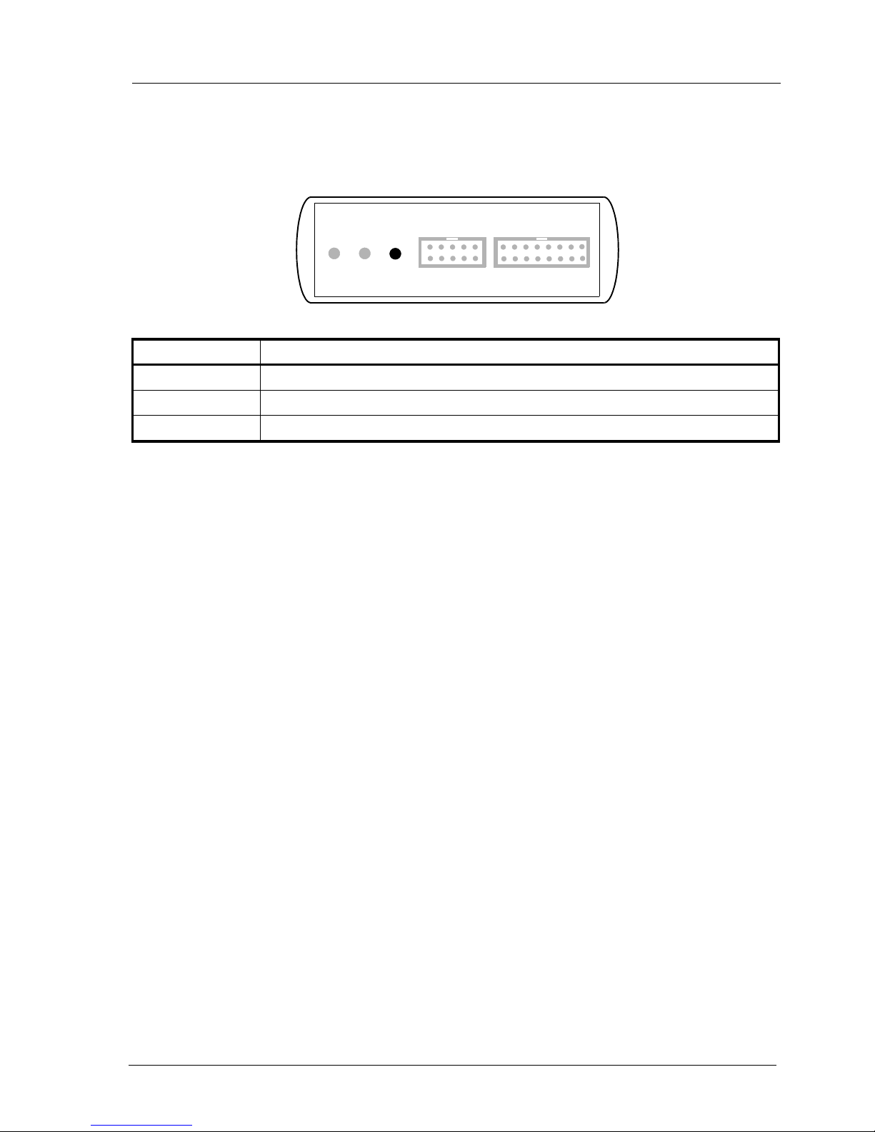
2.1 Connecting the BDI2000 to Target
The cable to the target system is a 16 pin flat ribbon cable. In case where the target system has an
appropriate connector, the cable can be directly connected. The pin assignment is in accordance with
the PowerPC 4xx JTAG connector specification.
In order to ensure reliable operation of the BDI (EMC, runtimes, etc.) the target cable length must not
exceed 20 cm (8").
For BDI TARGET B connector signals see table on next page.
!
JTAG Connector
BDI2000
Target System
PPC4xx 1 15
16
2
The green LED «TRGT» marked light up when target is powered up
BDI TRGT MODE TARGET A TARGET B
15 1
16 2
1 - TDO
2 - NC
3 - TDI
4 - TRST
5 - NC
6 - Vcc Target
7 - TCK
8 - NC
9 - TMS
10 - NC
11 - HALT
12 - NC (GROUND)
13 - NC
14 - NC (key)
15 - NC
16 - GROUND

bdiNDIJTAG debug interface for EDGE Debugger, BDI2000 (PPC4xx) User Manual 5
© Copyright 1992-2008 by ABATRON AG V 1.06
BDI TARGET B Connector Signals:
Pin Name Describtion
1TDO JTAG Test Data Out
This input to the BDI2000 connects to the target TDO pin.
2 <reseved>
3TDI JTAG Test Data In
This output of the BDI2000 connects to the target TDI pin.
4TRST JTAG Test Reset
This output of the BDI2000 resets the JTAG TAP controller on the target.
5 <reseved>
6 Vcc Target 1.8 – 5.0V:
This is the target reference voltage. It indicates that the target has power and it is also used
to create the logic-level reference for the input comparators. It also controls the output logic
levels to the target. It is normally fed from Vdd I/O on the target board.
3.0 – 5.0V with Rev. B :
This input to the BDI2000 is used to detect if the target is powered up. If there is a current
limiting resistor between this pin and the target Vdd, it should be 100 Ohm or less.
7TCK JTAG Test Clock
This output of the BDI2000 connects to the target TCK pin.
8 <reseved>
9TMS JTAG Test Mode Select
This output of the BDI2000 connects to the target TMS line.
10 <reseved>
11 HALT Processor Halt
This output of the BDI2000 connects to the target HALT line.
12 GROUND System Ground
13 <reseved>
14 <reseved>
15 <reseved>
16 GROUND System Ground

bdiNDIJTAG debug interface for EDGE Debugger, BDI2000 (PPC4xx) User Manual 6
© Copyright 1992-2008 by ABATRON AG V 1.06
2.1.1 Changing Target Processor Type
Before you can use the BDI2000 with an other target processor type (e.g. CPU32 <--> PPC), a new
setup has to be done (see Appendix A). During this process the target cable must be disconnected
from the target system. The BDI2000 needs to be supplied with 5 Volts via the BDI OPTION connec-
tor (Version A) or via the POWER connector (Version B). For more information see chapter 2.2.1
«External Power Supply».
To avoid data line conflicts, the BDI2000 must be disconnected from the target system while
programming the logic for an other target CPU.
!

bdiNDIJTAG debug interface for EDGE Debugger, BDI2000 (PPC4xx) User Manual 7
© Copyright 1992-2008 by ABATRON AG V 1.06
2.2 Connecting the BDI2000 to Power Supply
The BDI2000 needs to be supplied with 5 Volts (max. 1A) via the POWER connector. The available
power supply from Abatron (option) or the enclosed power cable can be directly connected. In order
to ensure reliable operation of the BDI2000, keep the power supply cable as short as possible.
For error-free operation, the power supply to the BDI2000 must be between 4.75V and 5.25V DC.
The maximal tolerable supply voltage is 5.25 VDC. Any higher voltage or a wrong polarity
might destroy the electronics.
Please switch on the system in the following sequence:
• 1 --> external power supply
• 2 --> target system
!
BDI TRGT MODE TARGET A TARGET B
POWER
1 - Vcc (+5V)
2 - VccTGT
3 - GROUND
4 - NOT USED
Connector
The green LED «BDI» marked light up when 5V power is connected to the BDI2000
RS232 POWER LI TX RX 10 BASE-T
1 Vcc
2
GND 3
4
Rev. B Version
bdiNDIJTAG debug interface for EDGE Debugger, BDI2000 (PPC4xx) User Manual 8
© Copyright 1992-2008 by ABATRON AG V 1.06
2.3 Status LED «MODE»
The built in LED indicates the following BDI states:
MODE LED BDI STATES
OFF The BDI is ready for use, the firmware is already loaded.
ON The power supply for the BDI2000 is < 4.75VDC.
BLINK The BDI «loader mode» is active (an invalid firmware is loaded or loading firmware is active).
BDI TRGT MODE TARGET A TARGET B

bdiNDIJTAG debug interface for EDGE Debugger, BDI2000 (PPC4xx) User Manual 9
© Copyright 1992-2008 by ABATRON AG V 1.06
2.4 Connecting the BDI2000 to the Host
2.4.1 Serial line communication
The host is connected to the BDI through the serial interface (COM1...COM4). The communication
cable between BDI and Host is a serial cable (RXD / TXD are crossed). There is the same connector
pinout for the BDI and for the Host side (Refer to Figure below).
RS232 Connector
(for PC host)
BDI2000
Target System
RS232
PC Host
1 - NC
2 - RXD data from host
3 - TXD data to host
4 - NC
5 - GROUND
6 - NC
7 - NC
8 - NC
9 - NC
RS232 POWER LI TX RX 10 BASE-T
54321
9876
MPC
8260

bdiNDIJTAG debug interface for EDGE Debugger, BDI2000 (PPC4xx) User Manual 10
© Copyright 1992-2008 by ABATRON AG V 1.06
2.4.2 Ethernet communication
The BDI2000 has a built-in 10 BASE-T Ethernet interface (see figure below). Connect an UTP (Un-
shilded Twisted Pair) cable to the BD2000. For thin Ethernet coaxial networks you can connect a
commercially available media converter (BNC-->10 BASE-T) between your network and the
BDI2000. Contact your network administrator if you have questions about the network.
The following explains the meanings of the built-in LED lights:
LED Name Description
LI Link When this LED light is ON, data link is successful between the UTP
port of the BDI2000 and the hub to which it is connected.
TX Transmit When this LED light BLINKS, data is being transmitted through the UTP
port of the BDI2000
RX Receive When this LED light BLINKS, data is being received through the UTP
port of the BDI2000
10 BASE-T
PC Host
Target System
Ethernet (10 BASE-T)
1 - TD+
2 - TD-
3 - RD+
4 - NC
5 - NC
6 - RD-
7 - NC
8 - NC
Connector
BDI2000
RS232 POWER LI TX RX 10 BASE-T
18 PPC
Autres manuels pour BDI2000
10
Table des matières
Autres manuels Abatron Accessoires informatiques


