Abatron BDI2000 Manuel utilisateur

bdiGDB
JTAG debug interface for GNU Debugger
PowerPC 7440 / 7450 / 86xx
User Manual
Manual Version 1.13 for BDI2000
©1997-2015 by Abatron AG

bdiGDBfor BDI2000 (PowerPC 7440/7450/86xx) User Manual 2
© Copyright 1997-2015 by ABATRON AG Switzerland V 1.13
1 Introduction ................................................................................................................................. 3
1.1 BDI2000................................................................................................................................. 3
1.2 BDI Configuration ..................................................................................................................4
2 Installation ................................................................................................................................... 5
2.1 Connecting the BDI2000 to Target ........................................................................................5
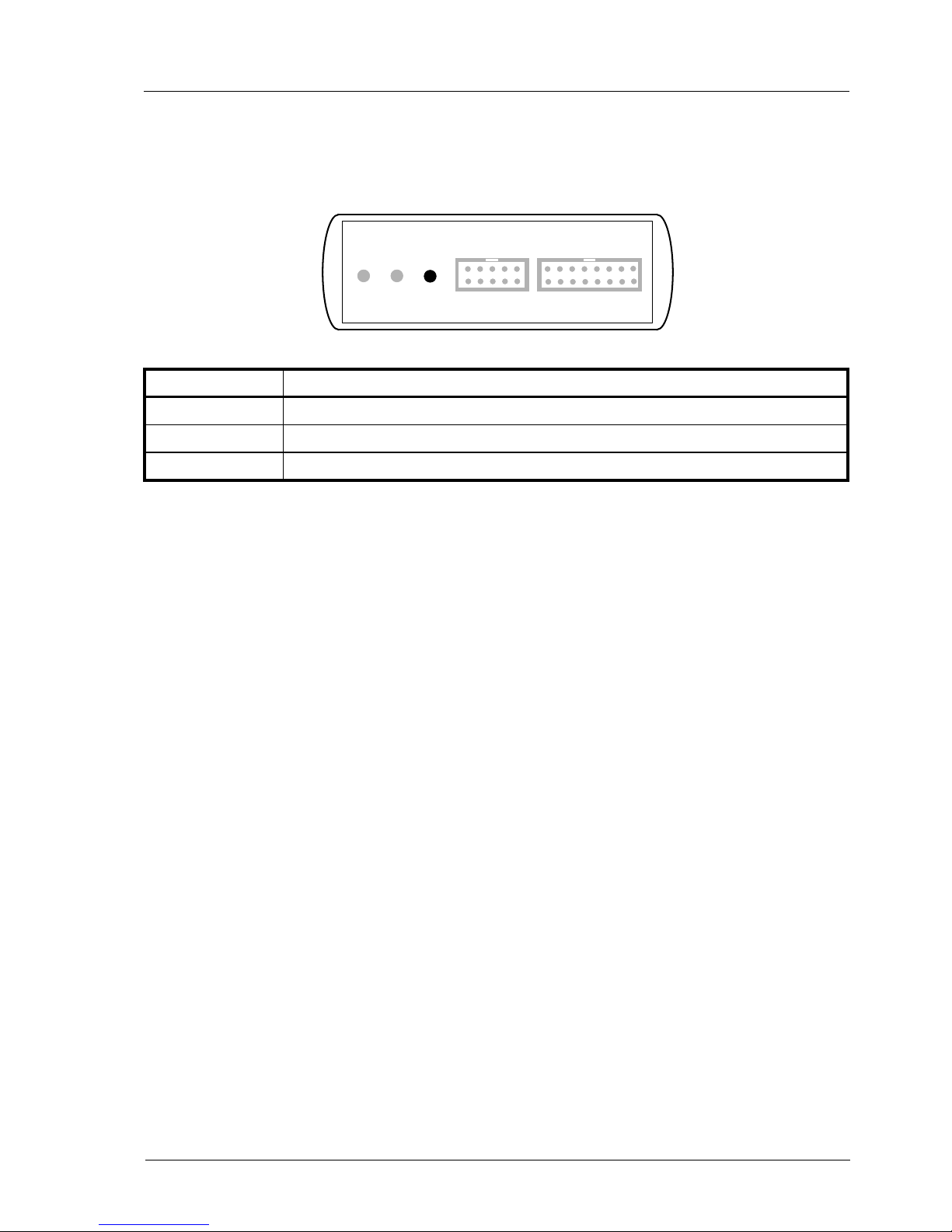
2.1.1 Changing Target Processor Type ................................................................................7
2.2 Connecting the BDI2000 to Power Supply ............................................................................ 8
2.3 Status LED «MODE».............................................................................................................9
2.4 Connecting the BDI2000 to Host .........................................................................................10
2.4.1 Serial line communication ..........................................................................................10
2.4.2 Ethernet communication ............................................................................................ 11
2.5 Initial configuration of the bdiGDB system...........................................................................12
2.5.1 Configuration with a Linux / Unix host........................................................................13
2.5.2 Configuration with a Windows host ............................................................................15
2.5.3 Recover procedure.....................................................................................................16
2.6 Testing the BDI2000 to host connection..............................................................................17
2.7 TFTP server for Windows....................................................................................................17
3 Using bdiGDB ............................................................................................................................ 18
3.1 Principle of operation...........................................................................................................18
3.2 Configuration File.................................................................................................................20
3.2.1 Part [INIT]...................................................................................................................21
3.2.2 Part [TARGET] ...........................................................................................................23
3.2.3 Part [HOST]................................................................................................................ 28
3.2.4 Part [FLASH] ..............................................................................................................30
3.2.5 Part [REGS] ............................................................................................................... 34
3.3 Debugging with GDB ...........................................................................................................36
3.3.1 Target setup ...............................................................................................................36
3.3.2 Connecting to the target.............................................................................................36
3.3.3 Breakpoint Handling...................................................................................................37
3.3.4 GDB monitor command..............................................................................................37
3.3.5 Target serial I/O via BDI.............................................................................................38
3.3.6 Embedded Linux MMU Support .................................................................................39
3.4 Telnet Interface....................................................................................................................41
3.5 Dual-Core Support for MPC8641D......................................................................................43
4 Specifications ............................................................................................................................ 45
5 Environmental notice................................................................................................................ 46
6 Declaration of Conformity (CE)................................................................................................ 46
7 Warranty..................................................................................................................................... 47
Appendices
A Troubleshooting ....................................................................................................................... 48
B Maintenance .............................................................................................................................. 49
C Trademarks ............................................................................................................................... 51

bdiGDBfor BDI2000 (PowerPC 7440/7450/86xx) User Manual 3
© Copyright 1997-2015 by ABATRON AG Switzerland V 1.13
1 Introduction
bdiGDB enhances the GNU debugger (GDB), with JTAG/COP debugging for PowerPC 7440/7450/
86xx based targets. With the built-in Ethernet interface you get a very fast code download speed. No
target communication channel (e.g. serial line) is wasted for debugging purposes. Even better, you
can use fast Ethernet debugging with target systems without network capability. The host to BDI
communication uses the standard GDB remote protocol.
An additional Telnet interface is available for special debug tasks (e.g. force a hardware reset,
program flash memory).
The following figure shows how the BDI2000 interface is connected between the host and the target:
1.1 BDI2000
The BDI2000 is the main part of the bdiGDB system. This small box implements the interface be-
tween the JTAG pins of the target CPU and a 10Base-T Ethernet connector. The firmware and the
programmable logic of the BDI2000 can be updated by the user with a simple Windows based con-
figuration program. The BDI2000 supports 1.8 – 5.0 Volts target systems (3.0 – 5.0 Volts target sys-
tems with Rev. B).
GNU Debugger
(GDB)
BDI2000
Target System
COP Interface
Ethernet (10 BASE-T)
PPC
7450

bdiGDBfor BDI2000 (PowerPC 7440/7450/86xx) User Manual 4
© Copyright 1997-2015 by ABATRON AG Switzerland V 1.13
1.2 BDI Configuration
As an initial setup, the IP address of the BDI2000, the IP address of the host with the configuration
file and the name of the configuration file is stored within the flash of the BDI2000.
Every time the BDI2000 is powered on, it reads the configuration file via TFTP.
Following an example of a typical configuration file:
;bdiGDB configuration file for Sandpoint 7450 evaluation system
;--------------------------------------------------------------
;
[INIT]
; init core register
;WREG MSR 0x00000000 ;clear MSR
; init memory controller (based on DINK32)
WM32 0xFEC00000 0x80000080 ;select MSAR1
WM32 0xFEE00000 0x00204060 ;
WM32 0xFEC00000 0x84000080 ;select MSAR2
WM32 0xFEE00000 0x80a0c0e0 ;
WM32 0xFEC00000 0x90000080 ;select MEAR1
WM32 0xFEE00000 0x1f3f5f7f ;
WM32 0xFEC00000 0x94000080 ;select MEAR2
WM32 0xFEE00000 0x9fbfdfff ;
WM32 0xFEC00000 0xa0000080 ;select MBEN
WM8 0xFEE00000 0x03 ;
WM32 0xFEC00000 0xa0000080 ;select MPM
WM8 0xFEE00003 0x32 ;
WM32 0xFEC00000 0xf0000080 ;select MCCR1
WM32 0xFEE00000 0x0000e075 ;do not set MEMGO
WM32 0xFEC00000 0xf4000080 ;select MCCR2
WM32 0xFEE00000 0xcc044004 ;
WM32 0xFEC00000 0xf8000080 ;select MCCR3
WM32 0xFEE00000 0x00004078 ;
WM32 0xFEC00000 0xfc000080 ;select MCCR4
WM32 0xFEE00000 0x39323235 ;
WM32 0xFEC00000 0xf0000080 ;select MCCR1
WM32 0xFEE00000 0x0000e875 ;now set MEMGO
;
WM32 0xFEC00000 0x78000080 ;select EUMBBAR
WM32 0xFEE00000 0x000000fc ;Embedded utility memory block at 0xFC000000
;
WM32 0xFEC00000 0xa8000080 ;select PICR1
WM32 0xFEE00000 0x901014ff ;enable flash write (Flash on processor bus)
;
[TARGET]
CPUTYPE 7450 ;the CPU type (7450)
JTAGCLOCK 1 ;use 8 MHz JTAG clock
WORKSPACE 0x00000000 ;workspace in target RAM for data cache flush and L3PM access
BDIMODE AGENT ;the BDI working mode (LOADONLY | AGENT | GATEWAY)
BREAKMODE SOFT ;SOFT or HARD, HARD uses PPC hardware breakpoint
DCACHE NOFLUSH ;data cache flushing (FLUSH | NOFLUSH)
[HOST]
IP 151.120.25.115
FILE E:\cygnus\root\usr\demo\mpc7450\vmlinux
FORMAT IMAGE
LOAD MANUAL ;load code MANUAL or AUTO after reset
Based on the information in the configuration file, the target is automatically initialized after every re-
set.

bdiGDBfor BDI2000 (PowerPC 7440/7450/86xx) User Manual 5
© Copyright 1997-2015 by ABATRON AG Switzerland V 1.13
2 Installation
2.1 Connecting the BDI2000 to Target
The cable to the target system is a 16 pin flat ribbon cable. In case where the target system has an
appropriate connector, the cable can be directly connected. The pin assignment is in accordance with
the PowerPC COP connector specification.
In order to ensure reliable operation of the BDI (EMC, runtimes, etc.) the target cable length must not
exceed 20 cm (8").
For BDI TARGET B connector signals see table on next page.
!
COP/JTAG Connector
BDI2000
Target System
PPC 1 15
16
2
The green LED «TRGT» marked light up when target is powered up
BDI TRGT MODE TARGET A TARGET B
15 1
16 2
1 - TDO
2 - QACK
3 - TDI
4 - TRST
5 - HALTED
6 - Vcc Target
7 - TCK
8 - NC (RXD)
9 - TMS
10 - NC (TXD)
11 - SRESET
12 - GROUND
13 - HRESET
14 - NC (key)
15 - CKSTP_OUT
16 - GROUND

bdiGDBfor BDI2000 (PowerPC 7440/7450/86xx) User Manual 6
© Copyright 1997-2015 by ABATRON AG Switzerland V 1.13
BDI TARGET B Connector Signals:
Pin Name Describtion
1 TDO JTAG Test Data Out
This input to the BDI2000 connects to the target TDO pin.
2QACK QACK
This output of the BDI2000 connects to the target QACK pin. By default this pin is not driven
by the BDI2000. With an entry in the configuration file it can be forced low.
3 TDI JTAG Test Data In
This output of the BDI2000 connects to the target TDI pin.
4TRST JTAG Test Reset
This output of the BDI2000 resets the JTAG TAP controller on the target.
5 IN0 General purpose Input
This input to the BDI2000 connects to the target HALTED pin. Currently not used.
6 Vcc Target 1.8 – 5.0V:
This is the target reference voltage. It indicates that the target has power and it is also used
to create the logic-level reference for the input comparators. It also controls the output logic
levels to the target. It is normally fed from Vdd I/O on the target board.
3.0 – 5.0V with Rev. B :
This input to the BDI2000 is used to detect if the target is powered up. If there is a current
limiting resistor between this pin and the target Vdd, it should be 100 Ohm or less.
7 TCK JTAG Test Clock
This output of the BDI2000 connects to the target TCK pin.
8 <reseved>
9 TMS JTAG Test Mode Select
This output of the BDI2000 connects to the target TMS line.
10 <reseved>
11 SRESET Soft-Reset
This open collector output of the BDI2000 connects to the target SRESET pin.
12 GROUND System Ground
13 HRESET Hard-Reset
This open collector output of the BDI2000 connects to the target HRESET pin.
14 <reseved>
15 IN1 General purpose Input
This input to the BDI2000 connects to the target CKSTP_OUT pin. Currently not used.
16 GROUND System Ground

bdiGDBfor BDI2000 (PowerPC 7440/7450/86xx) User Manual 7
© Copyright 1997-2015 by ABATRON AG Switzerland V 1.13
2.1.1 Changing Target Processor Type
Before you can use the BDI2000 with an other target processor type (e.g. CPU32 <--> PPC), a new
setup has to be done (see chapter 2.5). During this process the target cable must be disconnected
from the target system. The BDI2000 needs to be supplied with 5 Volts via the BDI OPTION connec-
tor (Version A) or via the POWER connector (Version B). For more information see chapter 2.2.1
«External Power Supply».
To avoid data line conflicts, the BDI2000 must be disconnected from the target system while
programming the logic for an other target CPU.
!

bdiGDBfor BDI2000 (PowerPC 7440/7450/86xx) User Manual 8
© Copyright 1997-2015 by ABATRON AG Switzerland V 1.13
2.2 Connecting the BDI2000 to Power Supply
The BDI2000 needs to be supplied with 5 Volts (max. 1A) via the POWER connector. The available
power supply from Abatron (option) or the enclosed power cable can be directly connected. In order
to ensure reliable operation of the BDI2000, keep the power supply cable as short as possible.
For error-free operation, the power supply to the BDI2000 must be between 4.75V and 5.25V DC.
The maximal tolerable supply voltage is 5.25 VDC. Any higher voltage or a wrong polarity
might destroy the electronics.
Please switch on the system in the following sequence:
• 1 --> external power supply
• 2 --> target system
!
BDI TRGT MODE TARGET A TARGET B
POWER
1 - Vcc (+5V)
2 - VccTGT
3 - GROUND
4 - NOT USED
Connector
The green LED «BDI» marked light up when 5V power is connected to the BDI2000
RS232 POWER LI TX RX 10 BASE-T
1 Vcc
2
GND 3
4
Rev. B Version

bdiGDBfor BDI2000 (PowerPC 7440/7450/86xx) User Manual 9
© Copyright 1997-2015 by ABATRON AG Switzerland V 1.13
2.3 Status LED «MODE»
The built in LED indicates the following BDI states:
MODE LED BDI STATES
OFF The BDI is ready for use, the firmware is already loaded.
ON The power supply for the BDI2000 is < 4.75VDC.
BLINK The BDI «loader mode» is active (an invalid firmware is loaded or loading firmware is active).
BDI TRGT MODE TARGET A TARGET B

bdiGDBfor BDI2000 (PowerPC 7440/7450/86xx) User Manual 10
© Copyright 1997-2015 by ABATRON AG Switzerland V 1.13
2.4 Connecting the BDI2000 to Host
2.4.1 Serial line communication
Serial line communication is only used for the initial configuration of the bdiGDB system.
The host is connected to the BDI through the serial interface (COM1...COM4). The communication
cable (included) between BDI and Host is a serial cable. There is the same connector pinout for the
BDI and for the Host side (Refer to Figure below).
RS232 Connector
(for PC host)
BDI2000
Target System
RS232
Host
1 - NC
2 - RXD data from host
3 - TXD data to host
4 - NC
5 - GROUND
6 - NC
7 - NC
8 - NC
9 - NC
RS232 POWER LI TX RX 10 BASE-T
54321
9876
PPC
Autres manuels pour BDI2000
10
Ce manuel convient aux modèles suivants
3
Table des matières
Autres manuels Abatron Accessoires informatiques


