a2b ETX-200 Manuel utilisateur
11
INSTALLATION
GUIDE
ETX-200
DVB-T Terrestrial Processor
design for TV
English

22
Contents
1. Introduction
2. Unpacking the unit
3. Connections and indications
4. Settings
5. About remultiplexing
6. Installation
7. SW options
8. SNMP
9. Technical specification
10.Declaration of conformity
11.Glossary
English

33
1 Introduction
Thank you for purchasing an A2B Electronics product. The ETX-200 is a
revolutionary solution for reception and modification of terrestrially transmitted
TV-content into various transmission formats for cable-TV and SMATV.
The ETX-200 is delivered with hardware and software that supports DVB-T
reception, MPEG2/MPEG4 H.264 AVC, ASI output, VSB RF modulation with
NICAM or A2 audio, SNMP Interface, IP control and management. All hardware
needed for upgrade with software options is available from the start. See
section 7 SW options for more information.
ETX-200 can be upgraded for enhanced functionality and various formats for
transmission and processing of digital-TV content by upgrade of its firmware.
Software options will be available from A2B Electronics, please ask us for the
specifications and complete price list of all options.
A2B Electronics AB
Phone: +46 (0)141 229115
E-mail: [email protected]
Also visit our web site www.a2b.se for further support.
English
44
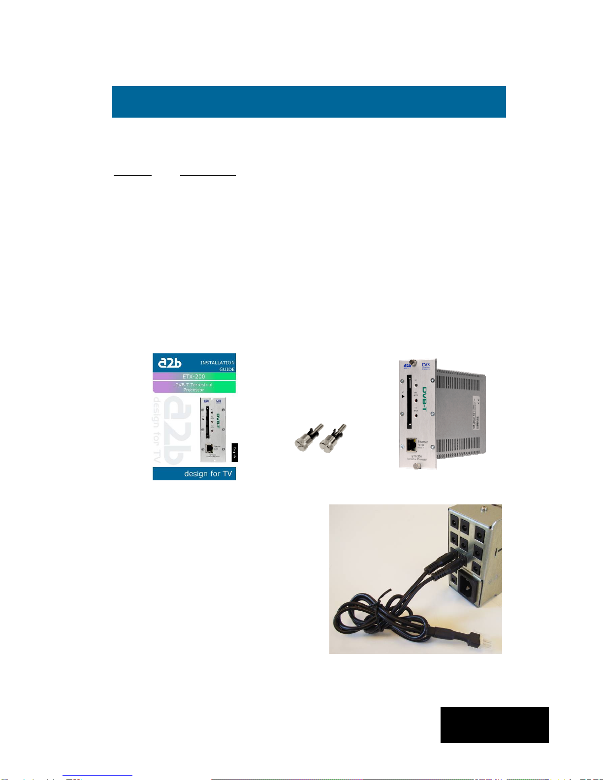
Following components are included in the package:
Amount Description
1 ETX-200 Terrestrial Processor
1 Installation guide
2 Front panel screws
NOTE! There is no SW CD, nor any Controll Software CD. The unit is
delivered with all necessary SW embedded including web server for control
and settings of the unit.
Every unit is quality controlled by us before delivery. Should any items be
missing when unpacking please contact our support service (see page 3 for
contact info).
English
2 Unpacking the unit
Important information about power
supply to ETX-200
To avoid problems with ETX-200 and/or
EPP-100 it is very important that both
DC plugs on the EXM power cord are
inserted into the EPP-100, i.e. each
EXM unit needs to be fed from two DC
outputs at the rear end of EPP-100.
(See picture to the right).
NOTE! Never connect two EPP units to
feed one ETX-200
55
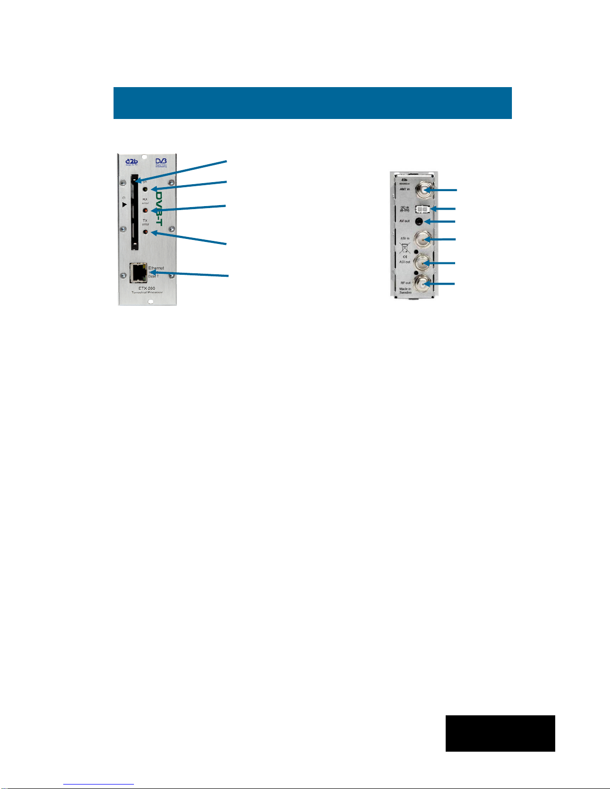
Common Interface Insert your Common Interface Conditional
Access module into this slot
Power on indicator Green light indicates that power is on.
Rx error Red light indicates that the receiver is not
locked to the terrestrial transmission.
Access/Tx error Red light indicates that the smart card is not
authorised or that decryption is not working
properly.
Ethernet port Ethernet for connection to a PC or handheld
device with web browser
Antenna in Connect your outdoor aerial to this input.
RF out Connection to Cable TV or SMATV network.
English
Ethernet port (RJ 45) for
control, settings
IPTV out and SNMP
Access/Tx error
indicator
Antenna
in
RF out
ASI out
COFDM Rx error
indicator
Power on indicator
Front panel view of
ETX-200
ASI in
DC in
Rear panel view of
ETX-200
3 Connections and indications
Common Interface slot
A/V out

66
A/V out *) Connection for monitoring or to an RF
modulator.
ASI in *) Input for ASI (Asynchronous Serial Interface)
for high speed transport stream reception.
ASI out Output for ASI (Asynchronous Serial Interface)
for high speed transport stream transmission.
DC in Connect a DC voltage to this input (6-10V).
*) Optional function i.e. SW option is needed
NOTE! We recommend to use only A2B original power supply
for correct functionality and life cycle. Warranty will be void in
case of damages caused by power supplies not supplied by A2B.
English
3 Connections and indications (continued)
ETX-200 has an embedded web
server allowing standard web
browsers
(Internet Explorer, Firefox, Opera
etc.) to connect to the unit for
settings and management.
No controller software is needed.
The ETX-200 has by default a static
IP address for connecting your PC to
the unit.
The ETX-200 is delivered with IP
address: 192.168.0.20. First time
installation requires that you set a
static IP address on your computer.
For example set your PC to IP
address: 192.168.0.19 and Net
mask: 255.255.255.0
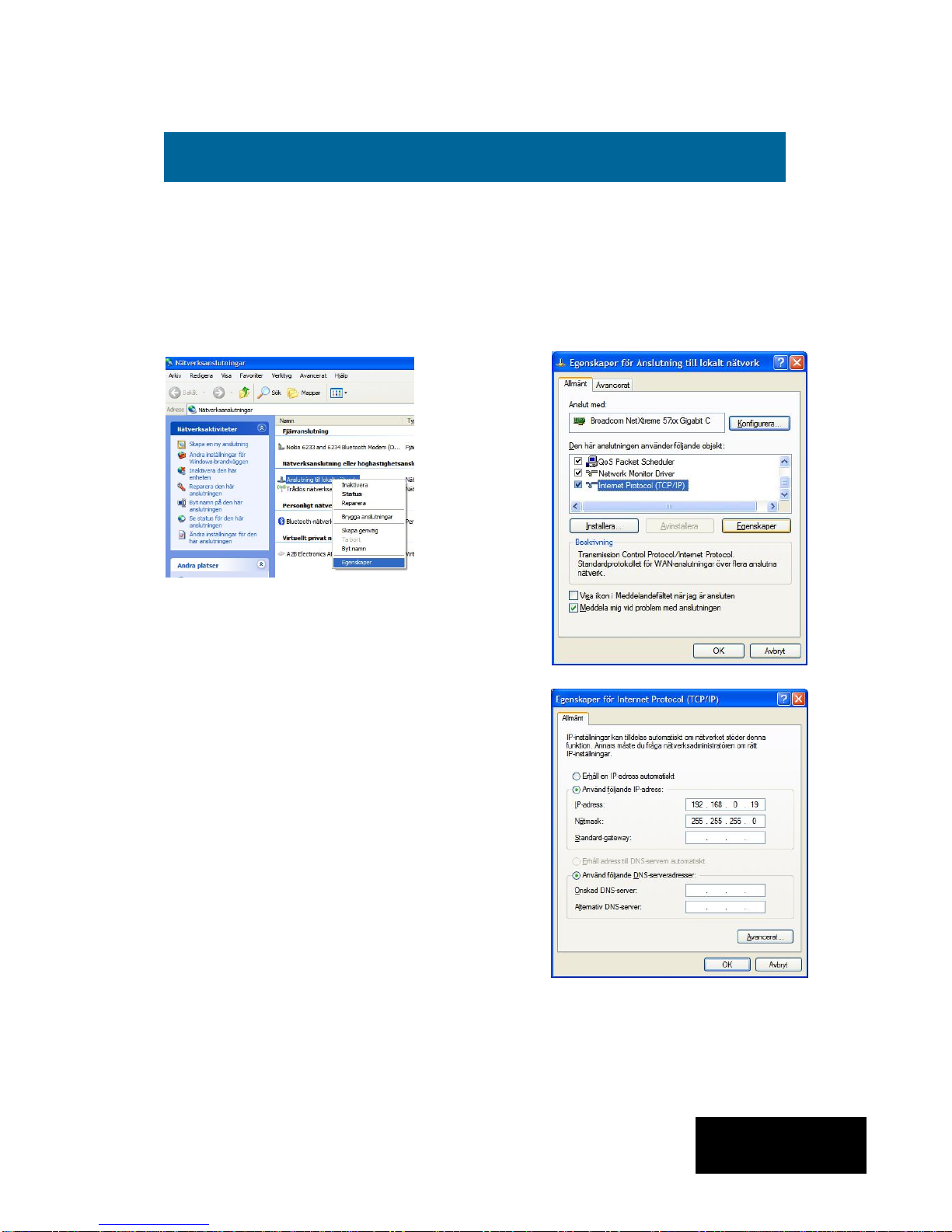
4 Settings
77
4.1 TCP/IP settings for Windows XP (setting your PC to 192.168.0.19)
Click ”Start”, select ”Control panel” and select ”Network connections” and then
select “Network and Internet settings”.”Right click” on [Settings for local network]
and select [Properties].
4 Settings (continued)
In Properties click [Internet protocol
(TCP/IP)] and select [Properties].
Select [Use this IP adress] and write:
192.168.0.19 and select [Net mask]
255.255.255.0. Click [OK] and then
click [Close].
NOTE! For PC with other Operating
Systems (OS) than Windows, please
consult the Owners manual for your PC
for [IP/Network settings].
4.2 Connecting your PC to ETX-200
Connect the ETX-200 to a DC power supply (EPP-100).
See section 6 for installation.
Next connect your PC to the ETX-200 with a network cable.
Start your web browser (IE, Firefox, Opera etc.) and write the
IP address 192.168.0.20 in the address field in your browser.
English
88
4.3 EXM Web Control Interface
4.3.1 System menu
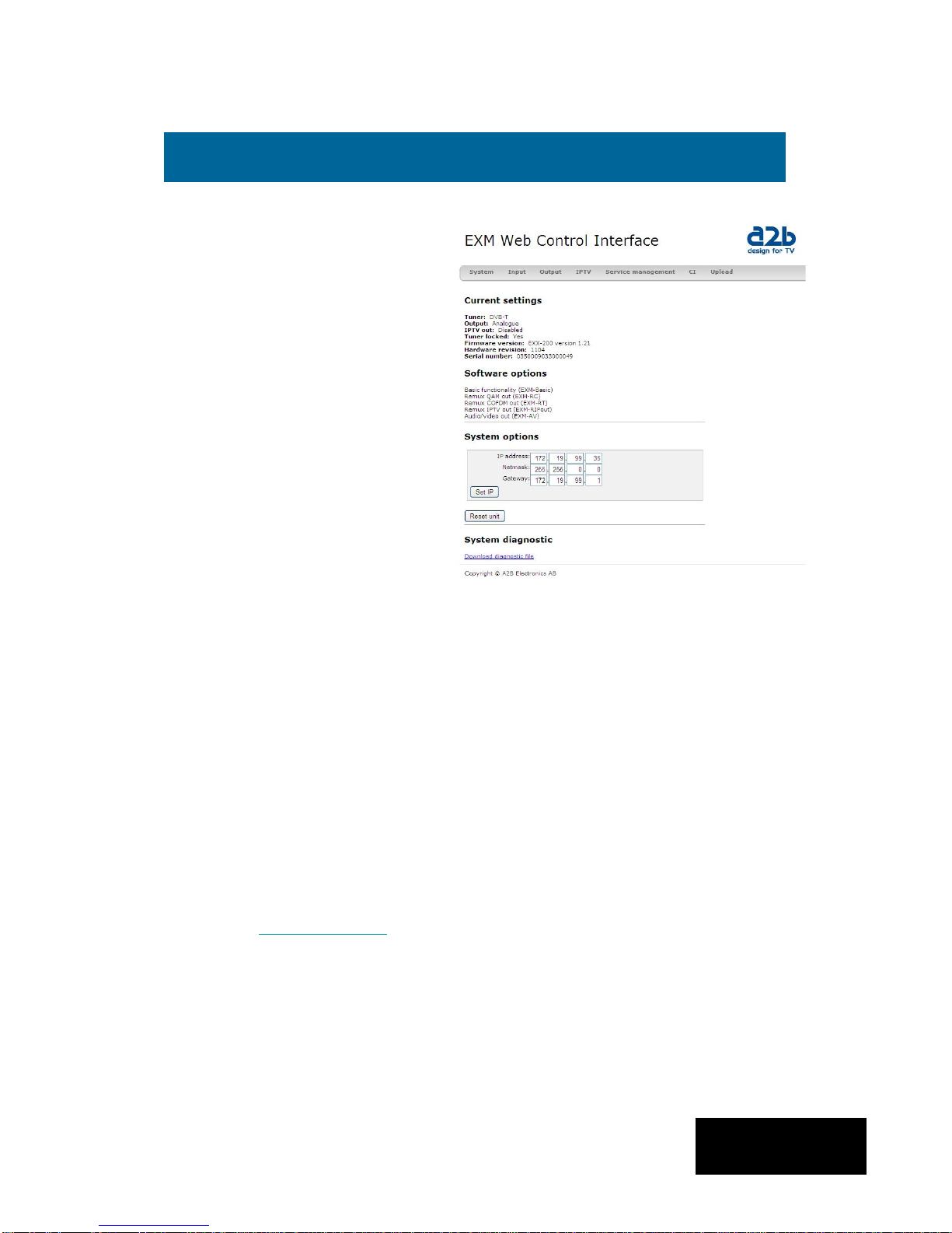
The following [System] menu
should appear when you connect
to the ETX-200. The [System]
menu contains basic information
about current settings and SW
options.
Menu buttons for [Input],
[Output], [IPTV],[Service
management], [CI] and [Upload]
are available at the top of the
menu.
4.3.2 IP address settings
The ETX-200 is set to an default IP address from factory (192.168.0.20 ). However, it
is possible to change the IP address and/or the Netmask and/or the Gateway. This is
an important function when you install two or more EXM units in a Head End and
want to connect all units together through a switch or a router.
4 Settings (continued)
Current settings
Contains information of current input and output signals, if the tuner is
locked to a signal, serial number and firmware revision.
Software options
Show what software options that are available in this unit (e.g. output
signal format, input signal etc.) See section 7 for more information.
System options
This menu contains current IP address for the ETX-200.
[Reset unit] gives a possibility to restart the unit at any time.
[System diagnostic]
By a click on the ”Download diagnostic file” you can save a file that you
English
99
IP address settings (continued)
Setting new static IP address in
the ETX-200
Connect your PC to each EXM
unit after that you have done all
other settings in the units and
change to a specific IP address
for every unit.
A recommendation is to use from
192.168.0.21 and higher.
NOTE! Almost every switch/router
use 192.168.0.1 as default IP
address so make sure you don’t
use the same IP address in any
ETX-200 unit.
To continue settings press [Input]
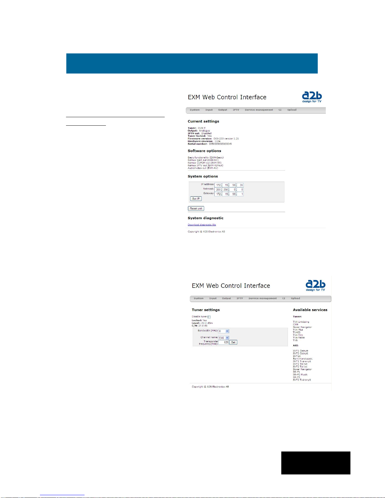
4.3.3 Tuner settings
Select the bandwith of the channel
you want to receive. Next select
the channel number according to
CCIR or enter the correct
frequency (in MHz). Be sure to
press [Set] to enter the frequency
to the ETX-200.
A list of the available services
from the multiplex you tuned to,
will be shown on the right hand
side.
Below [Tuner settings] information
of the received signal is displayed.
If only ASI in is used you can
Disable the tuner
Note! We recommend that the
[Level] reading is better than -55
dBm and C/N better than 25 dB for
best performance.
4 Settings (continued)
English
1010
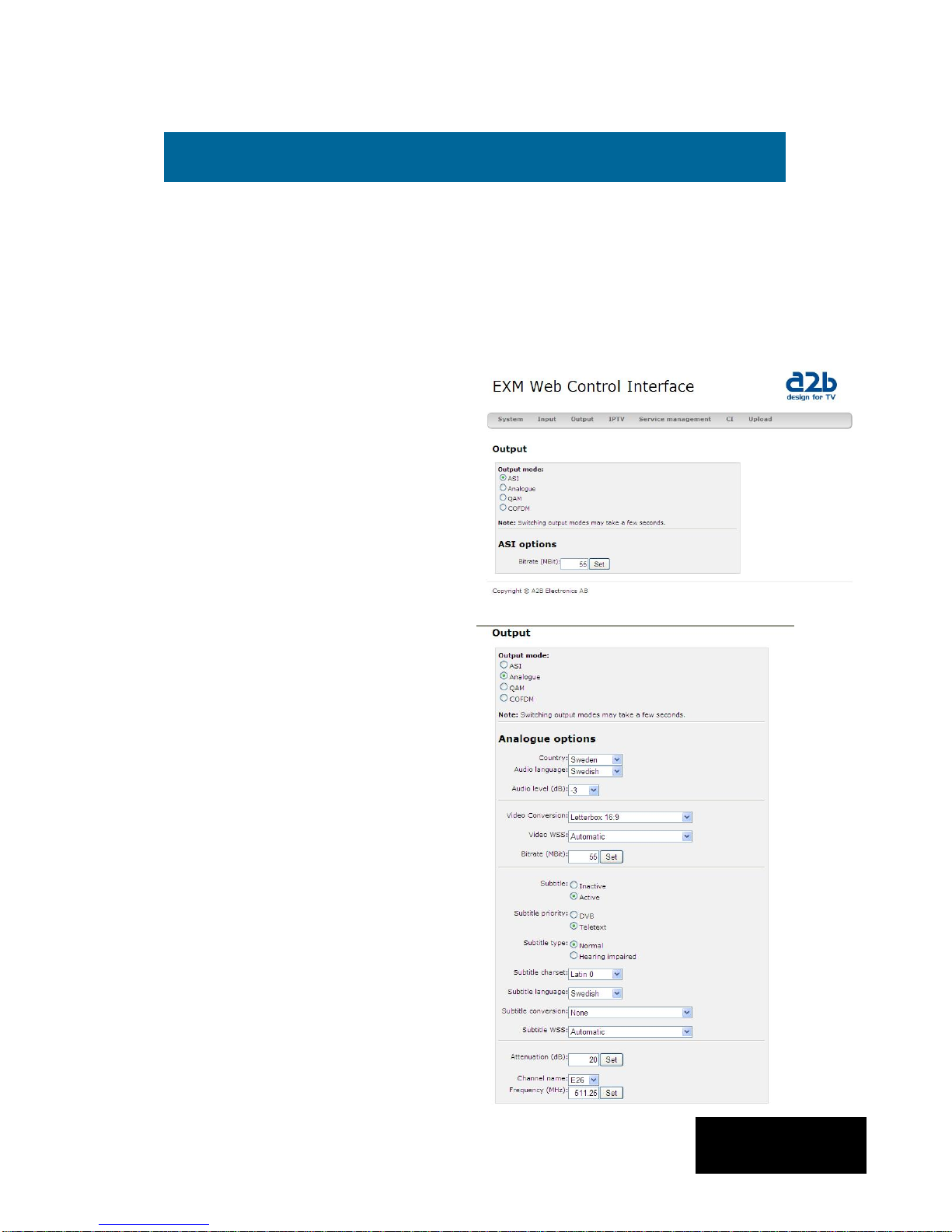
4.3.4 Output settings
ASI mode
The output selection ASI disables
all RF modulation on the outputs
and all selected services will be
transmitted only through the ASI
output connector. ASI is a high
speed interface for digital TV
transport streams. Use this output
mode if you run IPTV out.
Under [ASI options] you can select
the output bitrate which is the same
bitrate as for IPTV out.
Analogue mode
The selection [Analogue] is set as
factory default as RF output .
You can select output [Channel
name] (E2 to E69) or [Frequency]
within steps of 1 kHz (for example
306,167 MHz). Country specific
settings can be done by selecting
[Country]. By selecting a specific
country, transmission standard and
languages are automatically preset.
[Audio language] gives you the
choosen language if there is more
than one language ín the received
signal.
In this menu you can also do
settings for Subtitling priority, type,
charset, language, conversion and
subtitle WSS.
We suggest that you consult your local terrestrial operator for correct parameters
for each multiplex you want to receive.
Click [Output] to continue with the output settings.
4Settings (continued)
English
Table des matières
Autres manuels a2b Accessoires TV


