ZWAE OW Manuel
INSTALLATION AND SERVICE MANUAL
Zakład Wytwórczy Aparatów Elektrycznych Sp. z o.o.
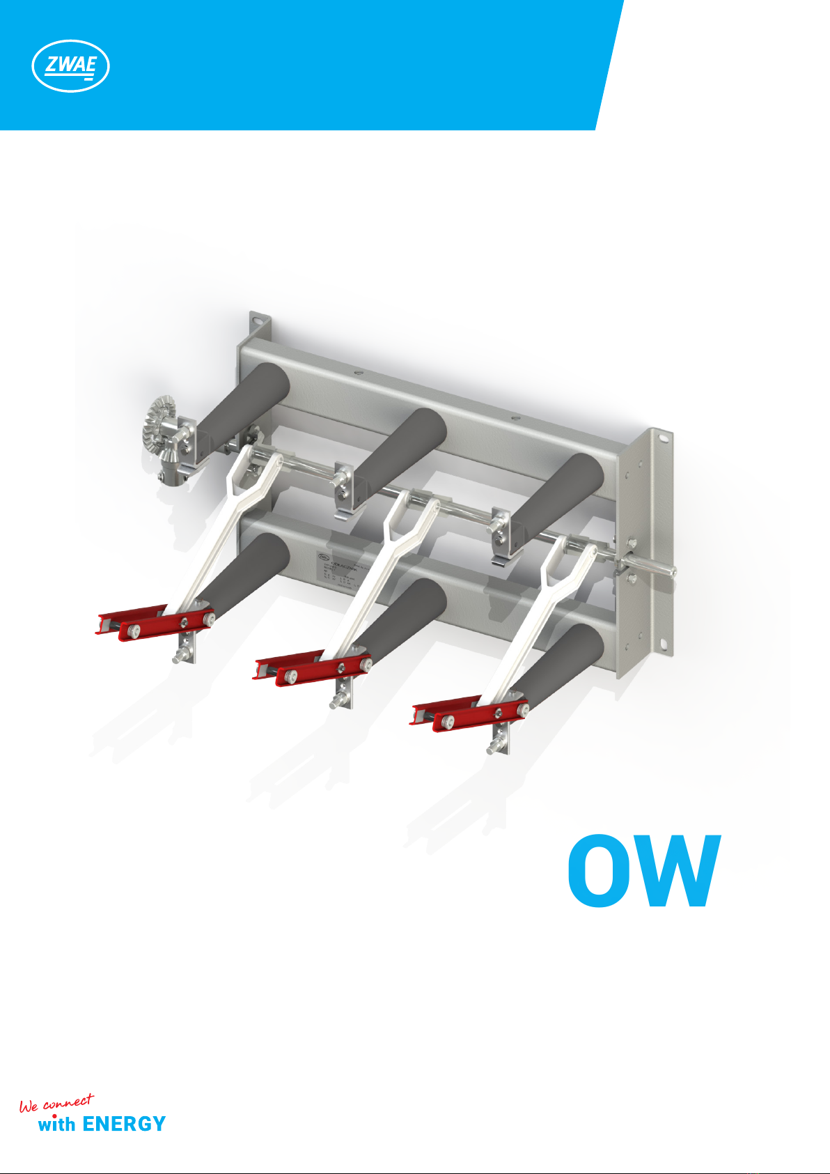
OW
Indoor disconnector
Manual Nr DTR.01.01.05.EN

Zakład Wytwórczy Aparatów Elektrycznych Sp. z o.o.
2
zwae.com.pl
WARNING!
During the operation of electrical equipment, certain parts of
these devices are normally under dangerous voltage, and me-
chanical parts, also remotely controlled, can move quickly.
Failure to follow the warning instructions can result in serious
personal injury or material damage.
Only suitably qualied personnel can work on or near the device.
This personnel must know exactly all safety rules and rules for
maintaining the device in accordance with these instructions.
The problem-free and safe operation of this device requires
proper transport, proper storage, construction and assembly as
well as careful service and maintenance.

Zakład Wytwórczy Aparatów Elektrycznych Sp. z o.o.
3
Table of Contents
1. TRANSPORT AND STORAGE . . . . . . . . . . . . . . . . . . . . . . . . . . . . 4
1.1. Unpacking and inspection ............................. 4
1.2. Transport and storage ................................. 5
2. DESCRIPTION ........................................ 6
2.1. Application ........................................... 6
2.2. Construction and principle of operation ................... 6
2.3. Ambient conditions during operation ..................... 7
2.4 . Nameplate ........................................... 7
3. ACCESSORIES, ADDITIONAL EQUIPMENT ................. 8
4. INSTALLATION AND ADJUSTMENT ...................... 10
4.1. Preparation of the supporting structure and
assembly of the disconnector............................... 10
4.2. Connecting feeding wires and grounding wire ............. 11
5. OPERATING MANUAL ................................. 13
5.1. Periodical check-ups................................... 13
5.2. Permited repairs carried out by the user .................. 13
6. MAINTENANCE ....................................... 13
6.1. Regular tests ......................................... 13
7. UTILIZATION ......................................... 14
Zakład Wytwórczy Aparatów Elektrycznych Sp. z o.o.
4
1. TRANSPORT AND STORAGE
1.1. Unpacking and inspection
Immediately after receiving the apparatus, check the delivery compliance with the packing list. Then check
whether the apparatus has not been mechanically damaged during transport and the check data on the name-
plate with the order.
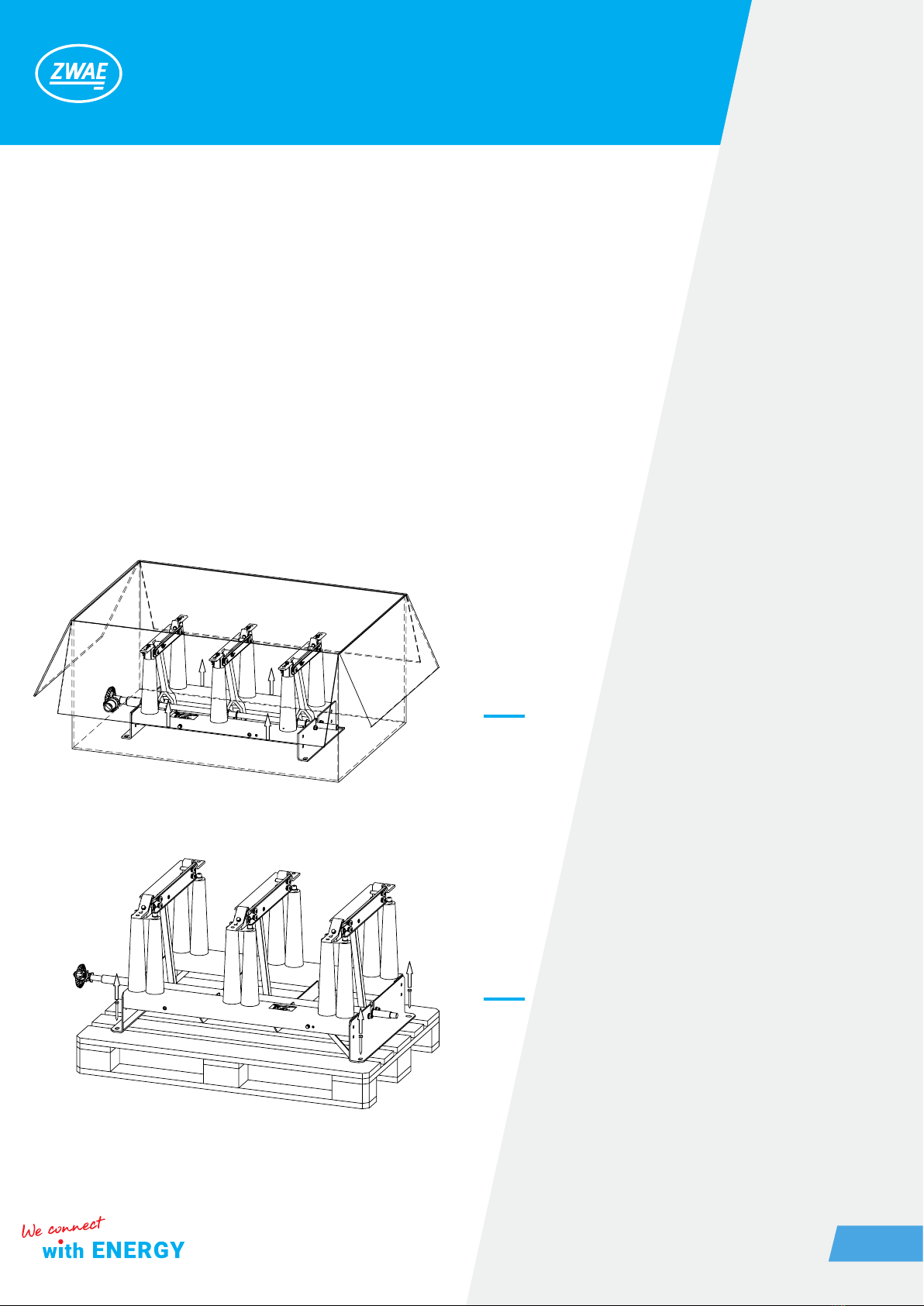
Disconnectors are delivered in the packaging or on a transport pallet to which they are screwed. When trans-
porting the disconnector, excessive shocks should be avoided.
Disconnectors are delivered to the customer completely assembled and adjusted.
Open the top of the packaging.
Pull the disconnector out by grabbing the base
frame.
It is unacceptable to lift the disconnector by
grabbing the current paths.
Before moving the disconnector from the pallet
to another place four screws have to be unscre-
wed.
Figure 1. Unpacking OWA disconnector and
taking it out from the packaging.
Figure 2. OWC disconnector on the transport
pallet screwed with screws.
Zakład Wytwórczy Aparatów Elektrycznych Sp. z o.o.
5
2
1
2
3
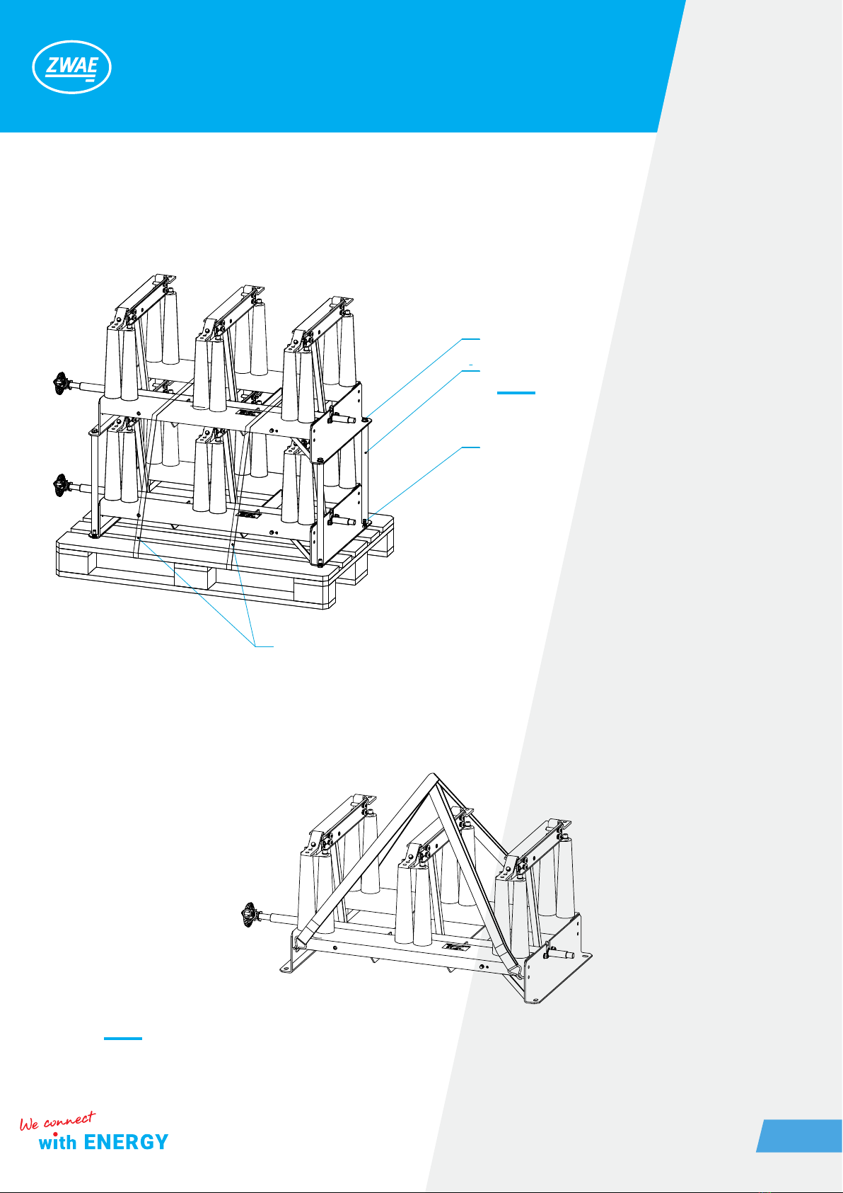
To take the disconnectors off the pallet, strap-
ping tapes have to be cut off (item 3). Then the
screws (item 2) have to be unscrewed from the
supports (item 1).
Figure 3. Two OWC disconnectors on supports,
fastened to the pallet with a tape.
1.2. Transport and storage
The disconnectors can be transported to a place of storage and installation by any means of transport pro-
vided they are protected against dripping water. During transport, disconnectors should be secured against
moving and colliding with each other or parts of the vehicle. It is not allowed to set the disconnectors directly
on top of each other. It may damage the disconnector. The disconnector should be moved using straps with
hooks as shown in gure below.
Figure 4 The way of moving the disconnector by a crane.
Zakład Wytwórczy Aparatów Elektrycznych Sp. z o.o.
6
2. DESCRIPTION
2.1. Application
The OW type disconnectors are designed for use in indoor MV switchgears. They are designed to close and
open electrical circuits in a off-load condition. In the open state, the disconnectors create a visible insulation
gap in the air, thus meeting the relevant requirements of standards for disconnectors.
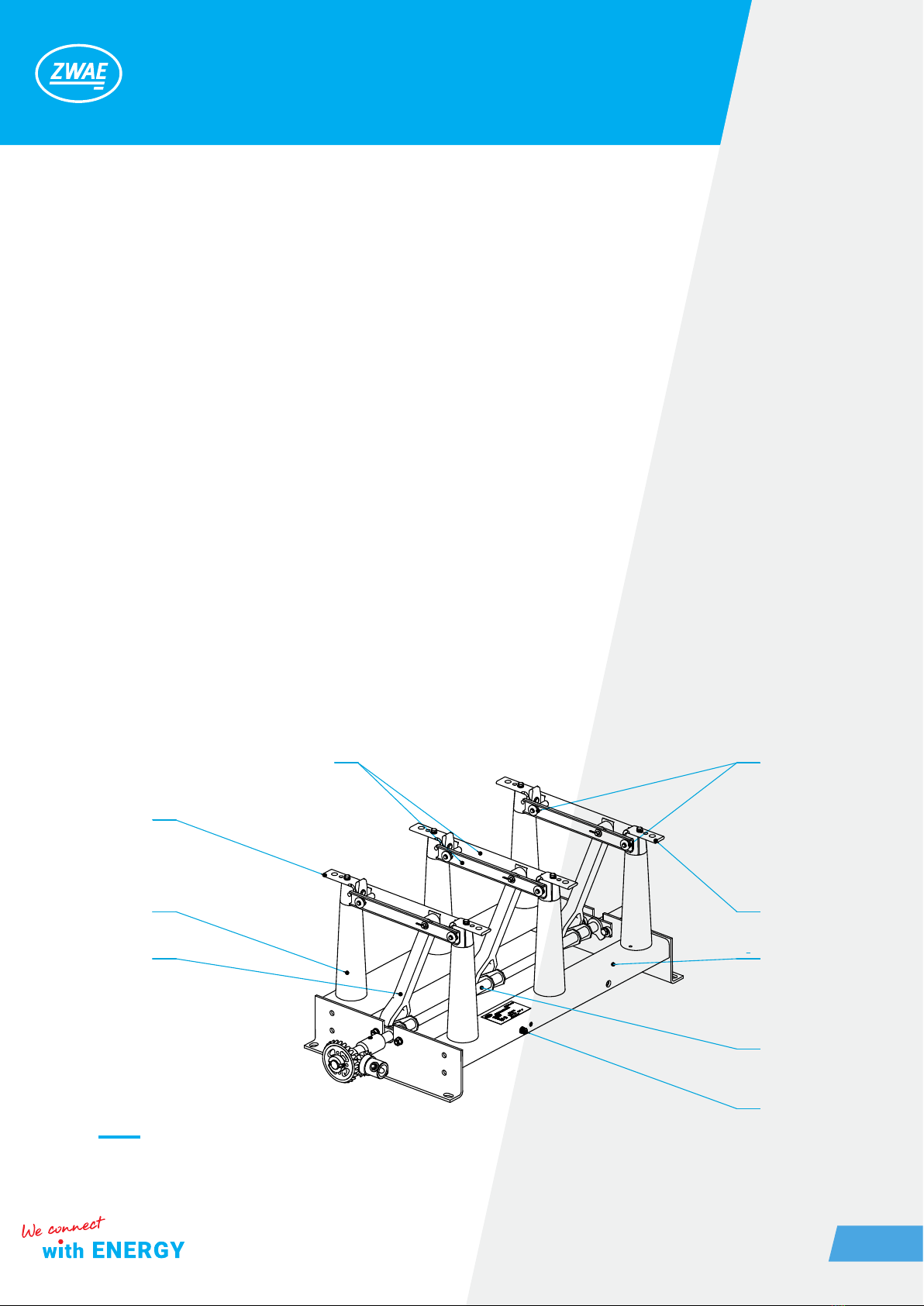
2.2. Construction and principle of operation
The OW type disconnectors are switches with a secant movement of the knives of the current path. The base of the
disconnector (item 1) is a welded steel frame in which sides the main shaft is mounted (item 2). On the transverse
shelves of the base there are resin support insulators (item 3), on which there is a disconnector‘s current path con-
sisting of two xed contacts (item 4) bolted to the insulators and moving contact (item 5). The moving contacts of
the current path are connected to the drive shaft by insulating rods (item 6). The rotary movement of the drive shaft
is transmitted trough insulating rods to the moving contacts, setting them in motion in a plane perpendicular to the
base. The blades pressure to the contacts is achieved by using springs (item 7). The disconnectors have a place to
connect the grounding connection (item 8). An additional equipment of disconnectors with a reduced pole spacing
are insulating barriers between poles.
Figure 5. Indoor disconnector type OWA-24/800 / Z / 275 (24 kV, 800 A)
1
2
8
7
5
4
3
6
4
Zakład Wytwórczy Aparatów Elektrycznych Sp. z o.o.
7
Ø
13
Ø13
Ø
12.5
16
4040
20
17
30
19
32
15
2.3. Ambient conditions during operation
Disconnectors type OWA, OWB, OWC are adapted for installation in indoor distribution devices, in which the
following ambient conditions exist:
- temperature within the range of: -5oC to + 40oC,
- relative air humidity (+30oC): 70%,
- for standard disconnectors, the maximum installation height above sea level: 1000 m.
2.4 . Nameplate
1. Manufacturer
2. Year of production
3. Rated current Ir =800 A
4. Rated duration of short-circuit tk [s]
5. Serial number
6. Rated operating voltage Ur[kV]
7. Surge test voltage Up [kV]
8. Rated short-circuit current Ik[kA]
9. Number of poles
10. Distance between poles 275 mm
11. Construction type
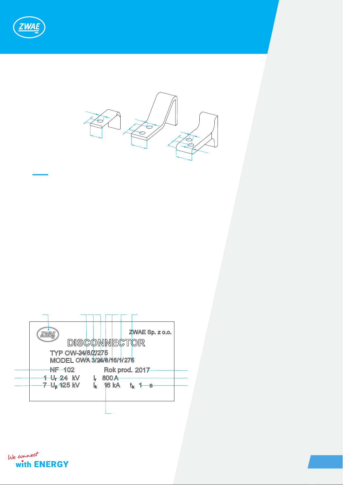
Figure 6. Types of contacts for disconnectors OWA, OWB, OWC
Disconnectors
OWB-12/800
OWA-17/800
OWA-24/800
Disconnectors
OWG-12/1600
OWG-12/2000
OWG-24/1600
Disconnectors
OWC-17/1600
OWC-36/1600
111 9 6 3 8 4
2
3
4
10
8
5
6
7
Zakład Wytwórczy Aparatów Elektrycznych Sp. z o.o.
8
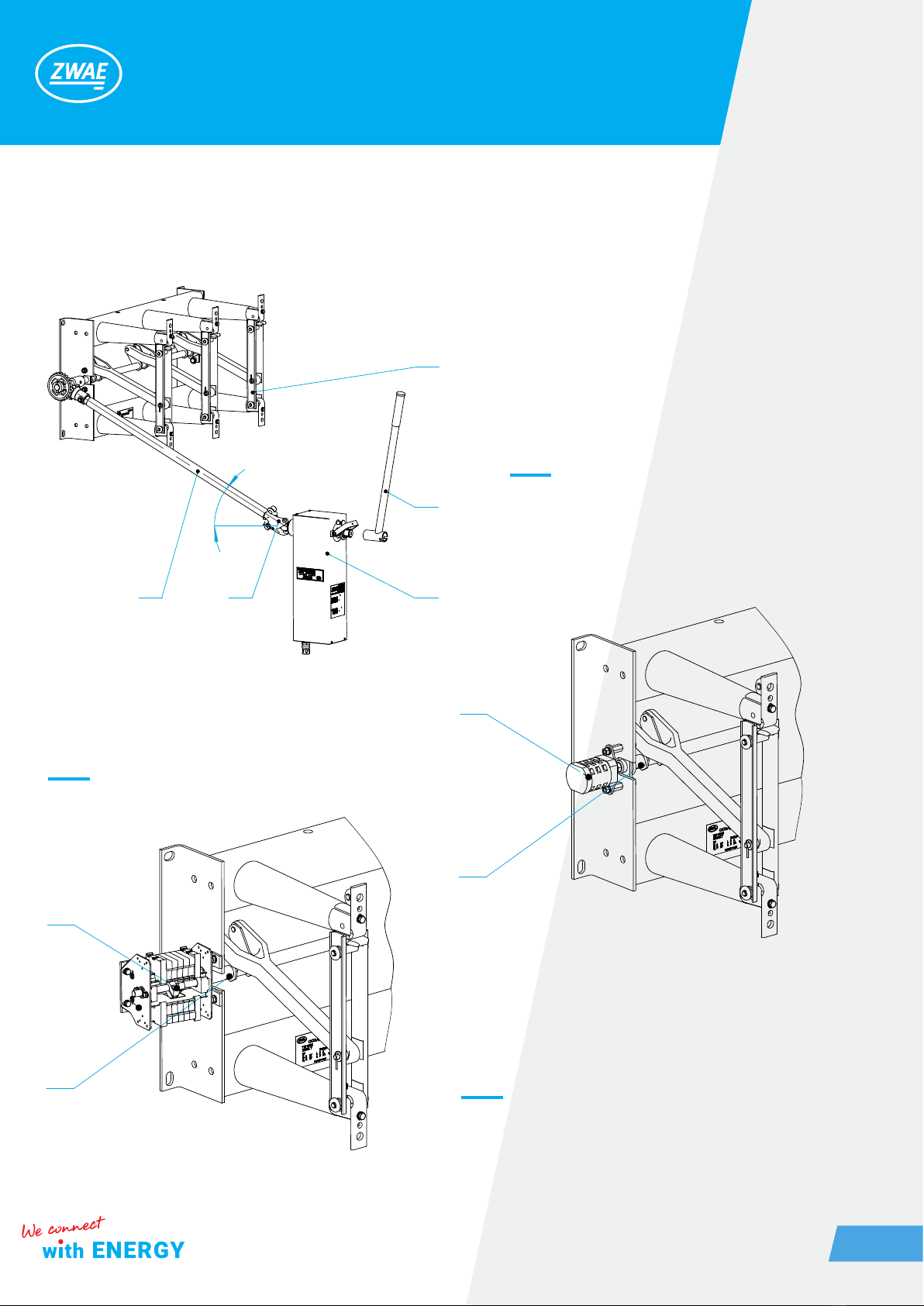
3. ACCESSORIES, ADDITIONAL EQUIPMENT
Figure 7. Connection of NSW30 operating mechanism
with disconnector
Figure 8. Connection of LK16 cam switch with disconnector
Figure 9. Connection of auxiliary switch LP1 with disconnector
1. Disconnector OWA
2. Operating mechanism NSW30
3. Driver lever
4. Terminal
5. Insulated driver rod
1. Cam switch LK16, number of contacts 3NO+3NC
2. Main shaft
1. Auxiliary switch LP1, max. number of contacts16 NO
+ 16 NC
2. Main shaft
1
3
2
54
0-30
2
1
1
2
Zakład Wytwórczy Aparatów Elektrycznych Sp. z o.o.
9
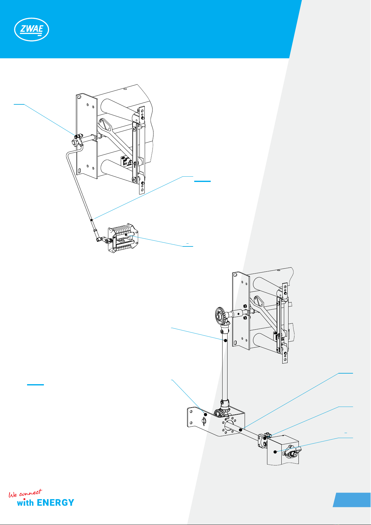
1. Auxiliary switch LP1, max. number of
contacts 16 NO + 16 NC
2. Tie rod
3. Lever
Figure 10. Connection of the auxiliary switch LP1
with the disconnector by means of a tie rod.
1. Operating mechanism NSW30
2. Terminal
3. Tie rod
4. Right angle gear
Figure 11. Connection of the disconnector with
an angle gear
1
2
3
3
2
1
4
3
Zakład Wytwórczy Aparatów Elektrycznych Sp. z o.o.
10
4. INSTALLATION AND ADJUSTMENT
Persons performing switching activities should have proper professional qualications and experience in ser-
vicing high-voltage equipment. When operating disconnector or its earthing switch (if installed) all health and
safety regulations in force at the place where they are installed have to be obeyed.
Before making a change (closing or opening) of the disconnector or its earthing switch one should ensure
that the adjustment is permissible, taking into account the conditions indicated above and the arrangement
conditions of the switchgear.
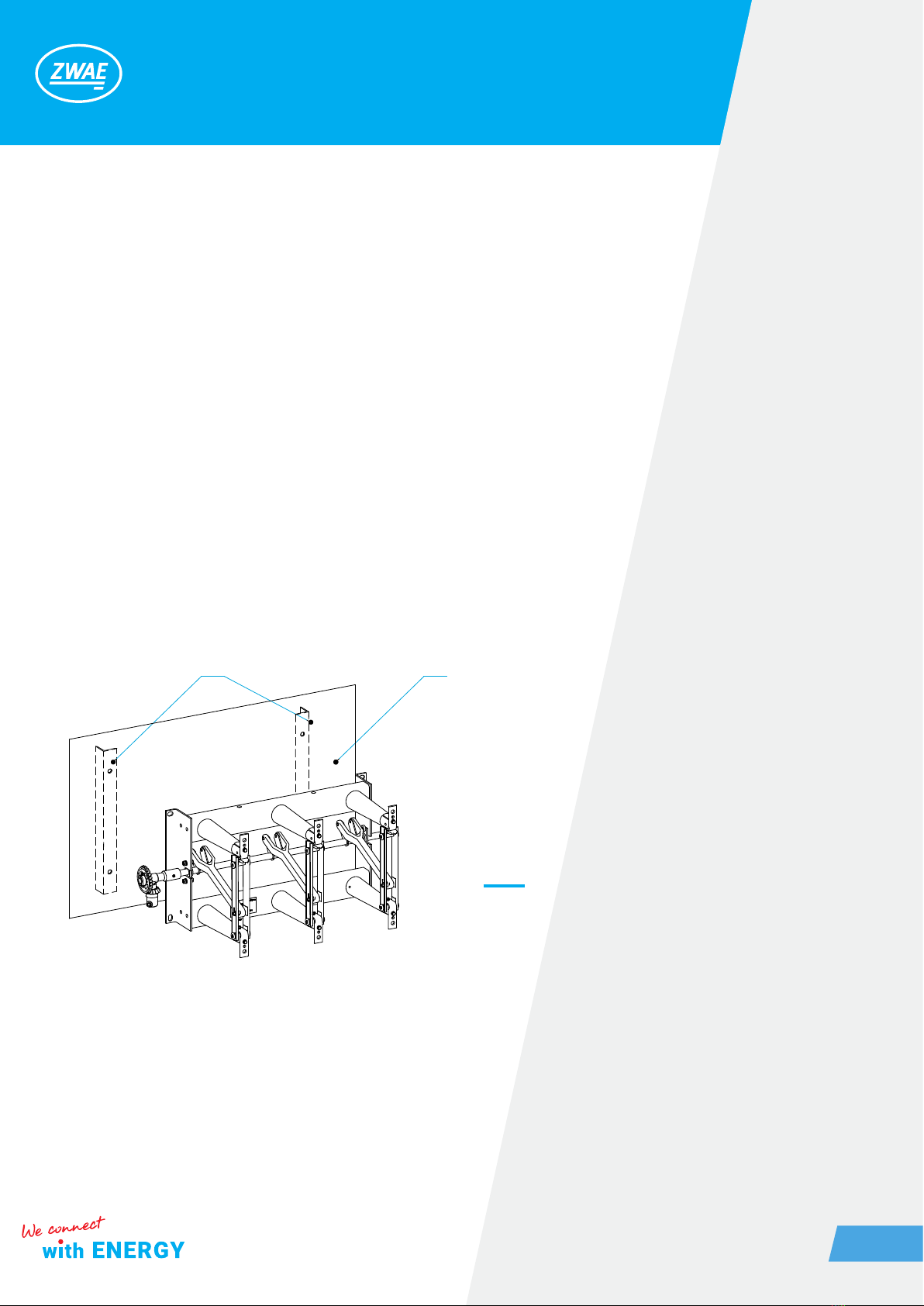
4.1. Preparation of the supporting structure and assembly of the disconnector
The OW type disconnectors are designed for operation in horizontal and vertical positions, with moving con-
tacts at the top. The design of the supporting structure should take into account the maintenance of appropri-
ate ground isolation distances, and the construction itself should have adequate stiffness.
The base of the disconnector should be pre-screwed in three places (with three M12 bolts), and then place
possible washers under the base to level the plane of the supporting structure. The contact points of the sup-
porting structure with the disconnector base should lie in one plane (pos.2).
1. Elements of the supporting structure
2. The plane in which contact points of the suppor-
ting structure should be located
Figure 12. Installation of the disconnector to the suppor-
ting structure.
1 2
Table des matières
Autres manuels ZWAE Équipement industriel


