ZOYI ZT-703S Manuel utilisateur

User Manual
All rights reserved; offenders will be prosecuted.
Specifications are subject to change without prior notice.

Limited Warranty and Scope of Rights and
Responsibilities
This product is eligible for a one-year
warranty from the date of purchase.
This warranty does not cover blown fuses,
damage to general accessories, or damage
caused by accidents, negligence, misuse,
modifications, pollution, and abnormal
operating environments.
Note: If there is a situation of freezing or
crashing during use, please restart.

Table of Contents
Title Page
Overview......................................................1
Safety Instructions...........................................1
Main Interface................................................3
Oscilloscope Mode Main Interface........................4
Panel Function Keys.....................................7
MENU interface..........................................8
Oscilloscope Functions Introduction...........................9
Probe Inspection........................................9
Safety..................................................9
Manual Compensation.....................................9
Probe Attenuation Setting..............................10
Channel Settings.......................................11
Auto Setup.............................................12
Vertical System........................................13
Horizontal System......................................13
Trigger System.........................................14
Numeric Measurement....................................15
XY Display Mode........................................16
Persistence Time.......................................16
Formatting.............................................16
Backlight Time.........................................16
Cursor Measurement.....................................17
How to Save and Review Measurement
Waveforms..............................................18

Operating Modes........................................19
Backlight Brightness...................................19
Baseline Calibration...................................19
Signal Generator Output Waveform Settings....................20
Multimeter Functions Introduction............................22
LCD Display Screen.....................................22
Multimeter Input Ports.................................24
Measurement Methods....................................25
Measurement of AC and DC Voltage.......................25
Measurement of AC and DC Current.......................25
Measuring Resistance...................................26
Measuring Continuity...................................26
Measuring Diodes.......................................27
Measuring Capacitance..................................27
Multimeter Extension Functions...............................28
Maintenance and Care.........................................29
Cleaning the Product.........................................29
Battery Charging.............................................29
Battery Storage..............................................30
Fuse Replacement.............................................30
Technical Specifications.....................................31
General Mechanical Environmental
Specifications...............................................31
Multimeter Specifications.............................32
Oscilloscope Specifications............................35

Overview
This handheld oscilloscope adopts a dual injection molding process,
featuring a beautiful appearance, compact size, convenient portability,
and flexible operation. The functional buttons have a clear and intuitive
menu interface. The screen utilizes a 3.5-inch IPS full-view color display,
with a multimeter display of up to 25,000 counts. This product
integrates the functions of an oscilloscope, signal generator, and
multimeter into a three-in-one device. With superior performance and
powerful functionality, it can be used in various measurement
scenarios, meeting a wide range of user measurement needs.
Safety Instructions
To avoid possible electric shock, fire hazards, and personal injury,
please read the safety precautions before using. Use the product only
for its designated purpose, as using it otherwise may compromise the
protection it provides.
Before using the product, check the housing for cracks or plastic
damage. Carefully inspect the insulation near the input ports. Follow
the instructions in this user manual, use the correct input ports, and set
the appropriate range as specified in this user manual for accurate
measurements.
Do not use this product in the presence of explosive gases and vapors or in
humid environments. Keep your fingers behind the protective shield of the
test probe.
1

•Do not touch unused input ports when the product is connected to
the circuit under test. Disconnect the test probes and the circuit
before changing the test range.
•When the DC voltage under test is higher than 36V, or the AC
voltage is higher than 25V, it may cause serious harm to the human
body; users should be cautious to avoid electric shock.
•Select the correct test range and scale to prevent damage to the
instrument or personal injury.
•Do not use this product with the front or rear cover open.
•Low battery voltage may affect the accuracy of test results; please
recharge promptly.
•The ground line between the two channels is the same, and during
measurements, the ground clip is always grounded or connected to
the same potential.
•The ground wire of the probe is at the same potential as the
ground. When connecting the USB cable for charging, it is
prohibited for the ground wire of the probe to touch high voltage,
as this may result in damage to the product or pose a risk of
injury.
•When using an oscilloscope probe to measure voltage higher than
(AC25V or DC36V), ensure that the USB protective cover of the
product is securely closed to prevent human contact with exposed
metal parts, as this could lead to the possibility of injury.
2
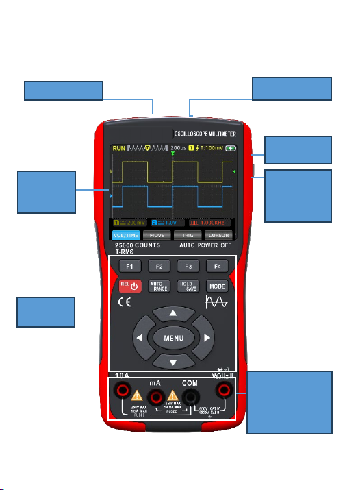
Main Interface
CH2 Input CH1 Input
USB
Interface
Display
Screen
Keys
Pad
Multimeter
Measurement
Input
Terminal
Signal
Generator
Output
Port
3
4
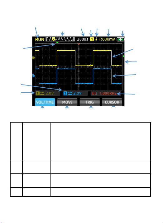
Oscilloscope Mode Main Interface
①②③④⑤ ⑥⑦
⑧⑨
⑩
⑪
⑫⑬⑭⑮
⑯
⑰
⑱
1
Operating
Status
Display
RUN: Automatic waveform acquisition state
WAIT: Normal trigger mode, blinking waiting
for trigger signal
T.D: Captured triggered waveform data
STOP: Lock the current waveform, acquisition
stopped
2Time Base
Window
Display current time base position within the
storage depth
3Time Base
Scale
Display the current set horizontal time base
scale value
4Trigger Trigger Channel:1 for CH1, 2 for CH2

5
7Battery
Level
Displaying the current battery status
and charging status.
8Horizontal
Trigger
Displaying the current horizontal
time base position triggered.
9Channel1 Showing the waveform of CH1 in
yellow.
10 Vertical
Trigger
Displaying the current vertical
voltage position triggered.
11 Channel 2 Showing the waveform of CH2 in blue.
12
Voltage/
Time Menu
(VOL/TIME)
In this menu, you can adjust channel
voltage and time base as follows:
Press F1 to switch channels; the menu
color will indicate the current
channel's color setting.
Press the up arrow to increase
voltage amplitude, and the down arrow
to decrease it.
Press the left arrow to decrease time
scale value, and the right arrow to
increase it.
13
Waveform
Movement
(MOVE)
Press F1 to switch channels; the menu
color will indicate the current
channel's color setting. Use the
arrow keys to adjust the waveform
position.
5Trigger
Mode
Display the current trigger mode as rising
edge or falling edge
6Level Display the current set trigger voltage value

6
14
Trigger
Cursor
(TRIGGER)
Press the up/down keys to adjust the
vertical trigger position and the
left/right keys to adjust the
horizontal trigger position.
15 Measurement
Cursor
Press this key to select the cursor
axis that needs adjustment.
16 CH1 Voltage Displaying the coupling mode and
voltage scale of Channel 1.
17 CH2 Voltage Displaying the coupling mode and
voltage scale of Channel 2.
18
Signal
Generator
Status
Showing the corresponding waveform
shape symbol and frequency setting
parameters according to the current
output status of the signal
generator, including square wave,
pulse wave, sine wave, and triangle
wave.
Table des matières
Autres manuels ZOYI Multimètre

Manuels Multimètre populaires d'autres marques


Gossen MetraWatt
Gossen MetraWatt METRAmax 6 Manuel utilisateur

PeakTech
PeakTech 4000 Manuel d'utilisation et d'entretien

YOKOGAWA
YOKOGAWA 90050B Manuel utilisateur

Gossen MetraWatt
Gossen MetraWatt METRALINE DMM16 Manuel utilisateur

Fluke
Fluke 8846A Manuel d'utilisation et d'entretien

Tempo Communications
Tempo Communications MM200 Manuel utilisateur


