
Yukon Eagle SUPER JACK SJ125 Manuel utilisateur
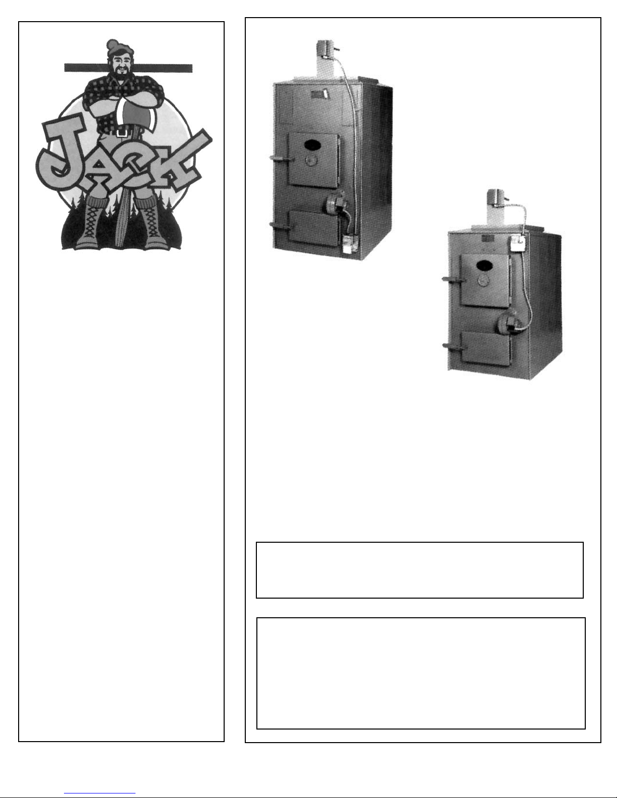
SUPER JACK/
BIG JACK
WOOD BURNING FURNACES
FOR YOUR SAFETY:
Do not store or use gasoline or other flammable vapors
and liquids in the vicinity of this or any other appliance.
Alpha American Co., 10 Industrial Blvd., Palisade, MN 56469
www.yukon-eagle.com
OWNER’S
MANUAL
• Assembly
• Installation
• Operation
• Repair Parts
Model No.’s
BJ90 - SJ125
CAUTION:
Read Rules And Instructions
Carefully For Safe Operation
IMPORTANT:
Installation must be made in
accordance with state and local
ordinances which may differ
from this installation manual.
TESTED BY
WARNOCK HERSEY
INTERNATIONAL TO
U/L 391 STANDARDS
SUPER JACK
SJ125
BIG JACK
BJ90
2
3
TABLE OF CONTENTS
INTRODUCTION
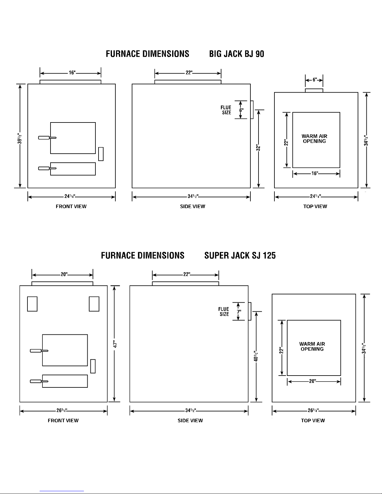
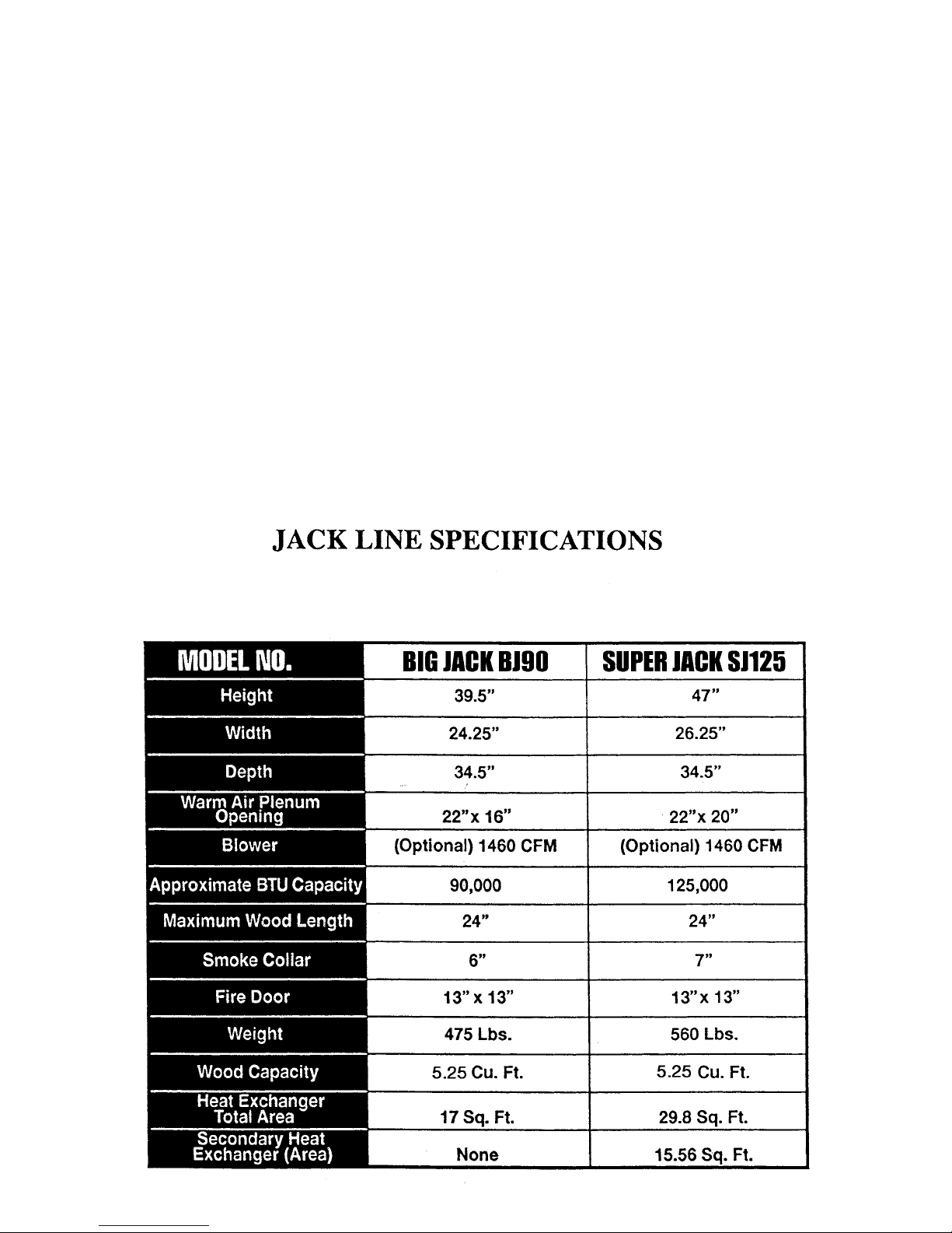
Furnace Specifications .......................................................... 3
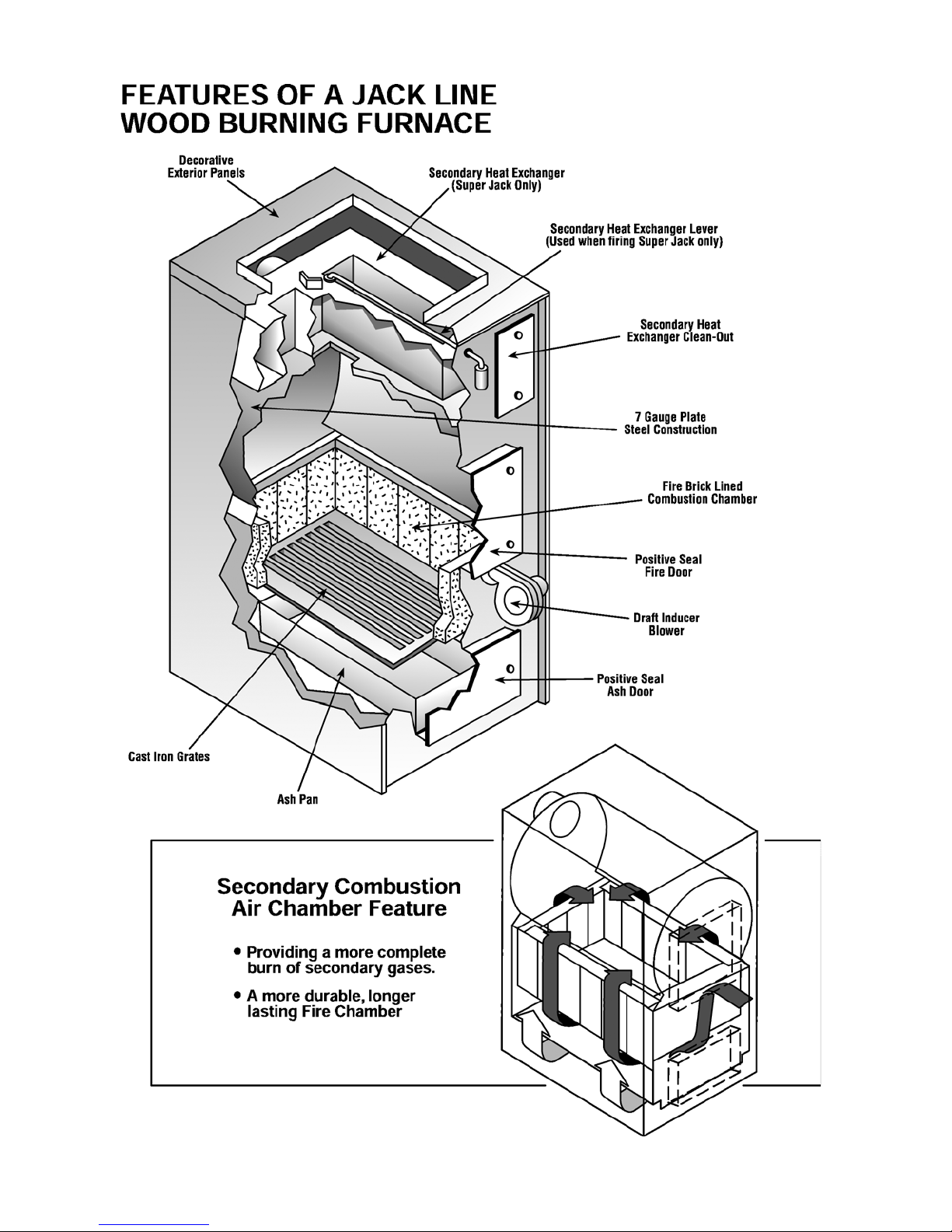
Features ................................................................................ 4
Dangers - Caution - Fire Hazards ......................................5-6
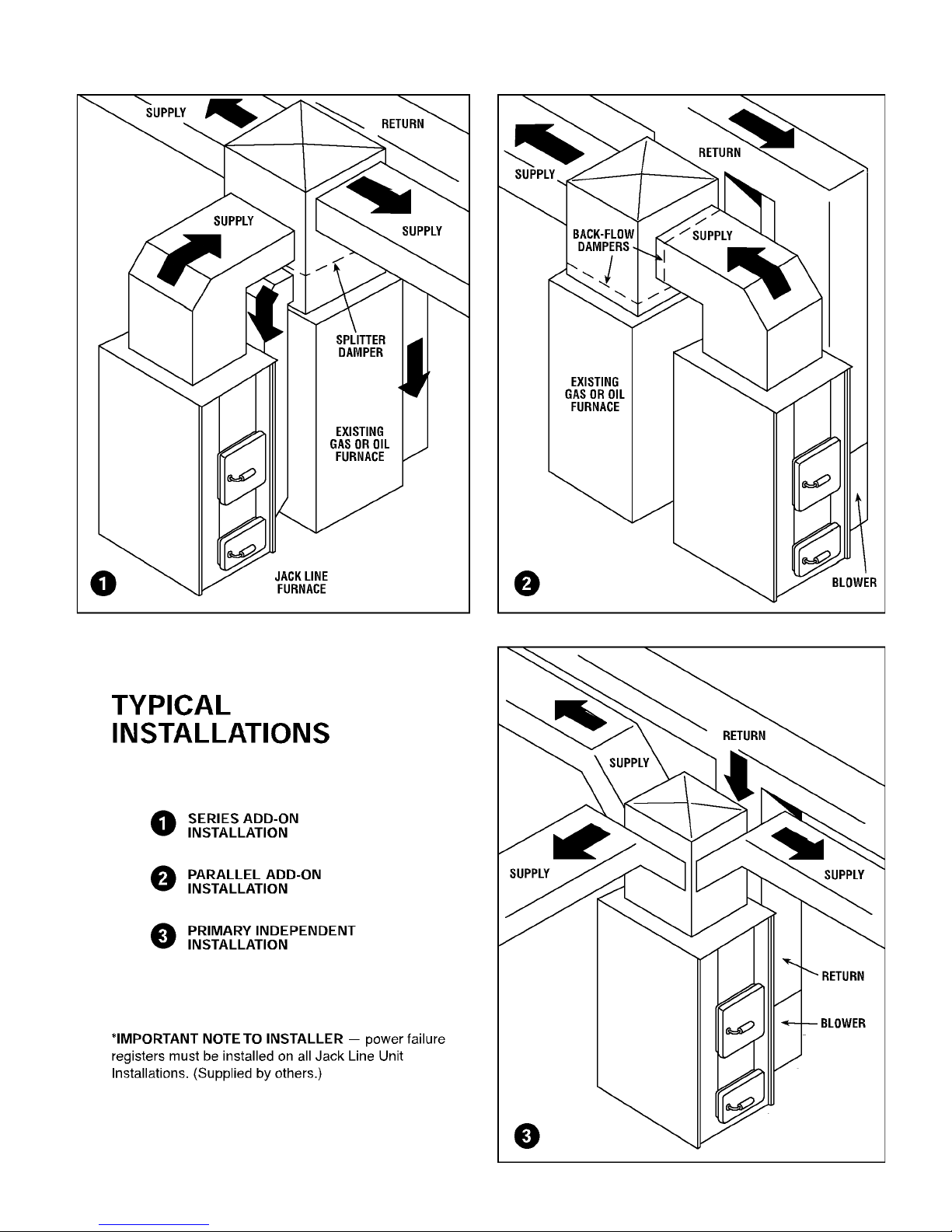
Typical Installation ................................................................. 7
Unpacking & Inspection......................................................... 8
Rules for Safe Installation and Operation ............................. 8
Locating the Furnace............................................................. 8
INSTALLATION
Furnace Casing ..................................................................... 9
Combustion Blower ............................................................... 8
Installing the Fan and Limit Control ..................................... 8
Electrical Wiring..................................................................... 4
Wiring the Furnace (Diagram) ....................................... 13
Mounting Thermostat............................................................. 9
Connecting Smoke Pipe and Barometric Damper Control
..... 9-10
Clearances to Combustibles ..............................................8-9
Ductwork Connection ............................................................ 9
Proper Chimneys................................................................... 9
Draft Regulator Location ..................................................... 10
Draft Regulator Installation.................................................. 10
Combustion Air .................................................................... 12
Causes of Faulty Draft ....................................................... .18
OPERATION
Wood Firing the Unit............................................................ 14
MAINTENANCE
Cleaning the Chimney, Smoke Pipe and Heat Exchanger.. 15
In Case of Chimney Fire ..................................................... 15
Service Hints ..................................................................16-17
Parts Breakdown ............................................................19-22
4

5
DANGER
RISK OF FIRE OR EXPLOSION
Do not burn garbage, gasoline, drain oil, kerosene, thinners, etc.
WARNING
RISK OF FIRE
- Firing door and ash door must be tightly closed during
operation.
- Do not operate with flue draft exceeding .03” W.C.
- Do not store flammable materials within marked installa-
tion clearances.
- Frequently inspect and clean heat exchanger, smoke pipe,
and chimney of soot and/or creosote.
- Do not connect this unit to a chimney flue serving another
appliance.
CAUTION
BLACK SURFACES ARE HOT
Keep children away. Do not touch.
6
DANGERS - CAUTION - FIRE HAZARDS
(Burn wood logs or coal only)
• This furnace must be installed according to the manu-
facturers instructions, NFPA and local codes.
• Ducts and plenums shall be constructed entirely of
sheet metal.
• Do not use flammable liquids to start a fire.
• Do not attempt to light a wood fire when gas or oil
vapors are present.
• Do not install on a burnable floor.
• In the event of an electrical power failure, be sure ash
door and fire door remain closed. Turn thermostat
down to shut off combustion fan.
• Do not install a power humidifier on warm air plenum.
• Store all ashes in a metal container with a tight fitting
lid. Allow ashes to cool before disposing of them.
• Be sure there is a sufficient supply of outside combus-
tion air to the area where the furnace is located.
• Keep smoke pipe connection as short as possible with
a minimum of 12-inch rise from the furnace to the
chimney opening. Smoke pipe should be 24 gauge
galvanized steel or heavier.
• This furnace has hot surfaces. Keep children away.
• Before servicing, allow furnace to cool. Shut off elec-
tricity.
• Familiarize yourself with this wood-burning furnace
before leaving it unattended.
• Follow a regular service and maintenance schedule of
furnace and chimney.
• IN THE EVENT OF A CHIMNEY FIRE, CALL FIRE
DEPARTMENT, AND THEN BE SURE ALL FURNACE
DOORS ARE CLOSED TIGHTLY.
Important: Make these adjustments when installing.
7
8
INTRODUCTION
This manual provides installation, operation, maintenance
instructions and parts ordering information for the Big Jack
Model BJ90 and the Super Jack Model SJ125 wood burning
furnaces.
IMPORTANT
Please read all instructions carefully before attempting
installation of this unit. Installation should only be done
by a qualified installer.
UNPACKING AND INSPECTION
Inspect the furnace for visible damage. The furnace is
shipped in one carton.
Inside the wood loading door is another carton. It contains
a gasket, conduit clip, wiring harness, fan and limit control,
transformer-relay, combustion blower and barometric draft
control.
A circulating blower, if ordered, is shipped in a separate
carton.
RULES FOR SAFE INSTALLATION AND OPERATION
1. Read these rules and the instructions carefully. Failure
to follow these rules and instructions could cause a
malfunction of the furnace. This could result in death,
serious bodily injury and/or property damage.
2. Check your local codes. The installation must com-
ply with them.
3. Use only the type of fuel approved for this furnace.
Over-firing will result in failure of heat exchanger and
cause dangerous operation.
4. You must have a sufficient supply of combustion air to
the area in which the furnace is located. (page 12)
5. Factory Built Chimneys: Connect this furnace to a
chimney that complies with NFPA 211 3-1.2. Factory
built chimneys for use with wood-burning appliances
shall comply with the HT requirements of UL 103 or
CAN/ULC-S629-M87. This means you must install
what is referred to as type HT all fuel chimney.
Masonry Chimneys: Connect this furnace to a chimney
that complies with NFPA 211 3-1.2. A field constructed
chimney of solid masonry units, bricks, stones, listed
masonry chimney units, or reinforced Portland cement
concrete that is lined with suitable chimney flue liners
and built in accordance with the provisions of Chapter
4 of this standard.
6. Follow a regular service and maintenance schedule
for efficient and safe operation.
7. Before servicing, allow furnace to cool. Always shut off
electricity and fuel to furnace when working on it. This
will prevent electrical shocks or burns.
LOCATING THE FURNACE
Locate the furnace as close to the chimney or flue as pos-
sible and near the center of the heat distribution system or
next to primary furnace if used.
Locate furnace where there is sufficient air supply for ven-
tilation and proper combustion to comply with the minimum
clearances required for fire protection and accessibility. See
page 7 for typical installations. See also Combustion Air.
(page 12)
NOTE
It is recommended that a 2", noncombustible raised pad
be used for the furnace. This will prevent moisture from
getting under the furnace and causing corrosion.
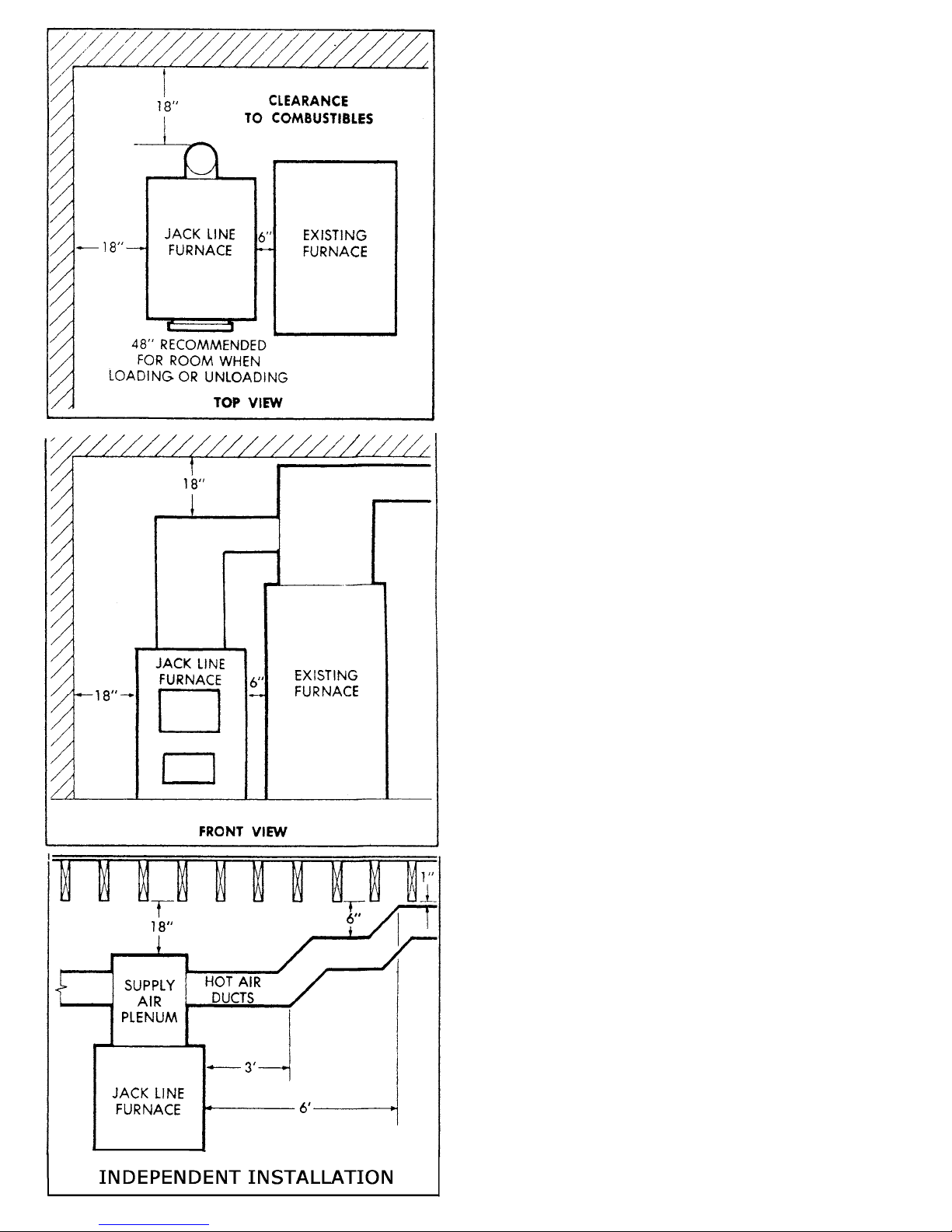
PLACEMENT AND MINIMUM CLEARANCES
For installation of our Jack Line furnace, the National Fire Protection
Association (NFPA) Standard 90B specifies the minimum standard
clearances to combustible surfaces as summarized below.
CLEARANCE CHART
Above Top of Plenum 18”
From the Front 48”
From Sides and Back 18”
From Flue Pipe 18”
From Existing Furnace 6 ”
From Horizontal Warm Air Duct:
Within 3 ft. of Plenum 18”
Within 3 to 6 ft. Plenum 6”
Beyond 6 ft. of Plenum 1”
All heat runs 1”
PARTS ASSEMBLY
1. Install the combustion blower & gasket to the provided
opening just below the wood-loading door on the front
of the furnace.
2. Attach the 4x4 junction box with the transformer/relay
to the mount provided at the top right hand side of the
front of the furnace.
3. Insert the fan-limit control into the sheet metal plenum
approximately 6 inches above the furnace.
4. Wire according to the enclosed wiring instructions &
local codes. (See page 13)
REDUCED CLEARANCES
Up to 50% less clearance between combustible walls and chimney
connector to furnace and ducts is allowed if insulated according to
NFPA Standard 90B or your local building code. This copyrighted
book is available from the National Fire Protection Association Inc.
1 Batterymarch Park, Quincy, MA. 02169-7471. Phone orders:
1-800-344-3555. Their internet address is www.nfpacatalog.org.
It is a mistake to assume that sheet metal, masonry, or asbes-
tos-like board placed directly against a wall protects it. Materials
installed in this manner give very little protection. These materials
are good conductors, so they will be almost as hot on their back-
side as well as on their exposed side. Therefore, the combustible
wall behind it is still a fire hazard.
CAUTION
Do not use any smoke pipes less than 24 gauge between
furnace and chimney.
CONNECTING SMOKE PIPE
Set the smoke pipe end of the furnace as close to the chimney as
possible. For every foot of lateral pipe, the rise of the smoke pipe
toward the chimney must be at least one inch. Do not exceed 10
feet in length. A cleanout tee should be installed for removal of
soot and fly ash.
Do not install the smoke pipe longer than necessary to reach the
chimney for purposes of trapping heat. The smoke outlet tempera-
ture is designed so that the heat emitted is needed to carry the
by-products of combustion out through the chimney.
The smoke pipe must not pass through any combustible material.
The smoke pipe entrance into a masonry chimney should be at
least 2 feet above the cleanout. The smoke pipe must not extend
into the chimney beyond the inner face of the chimney liner.
WARNING
Check your chimney. The chimney is a very important part
of your heating system. It must be the right size, properly
constructed and in good condition. No furnace can function
properly with a bad chimney. The chimney must supply a draft
of .03 Water Column. If possible, use a 15 foot or higher chim-
ney. Add an additional foot to the chimney for each 1,000 feet
of elevation above sea level.
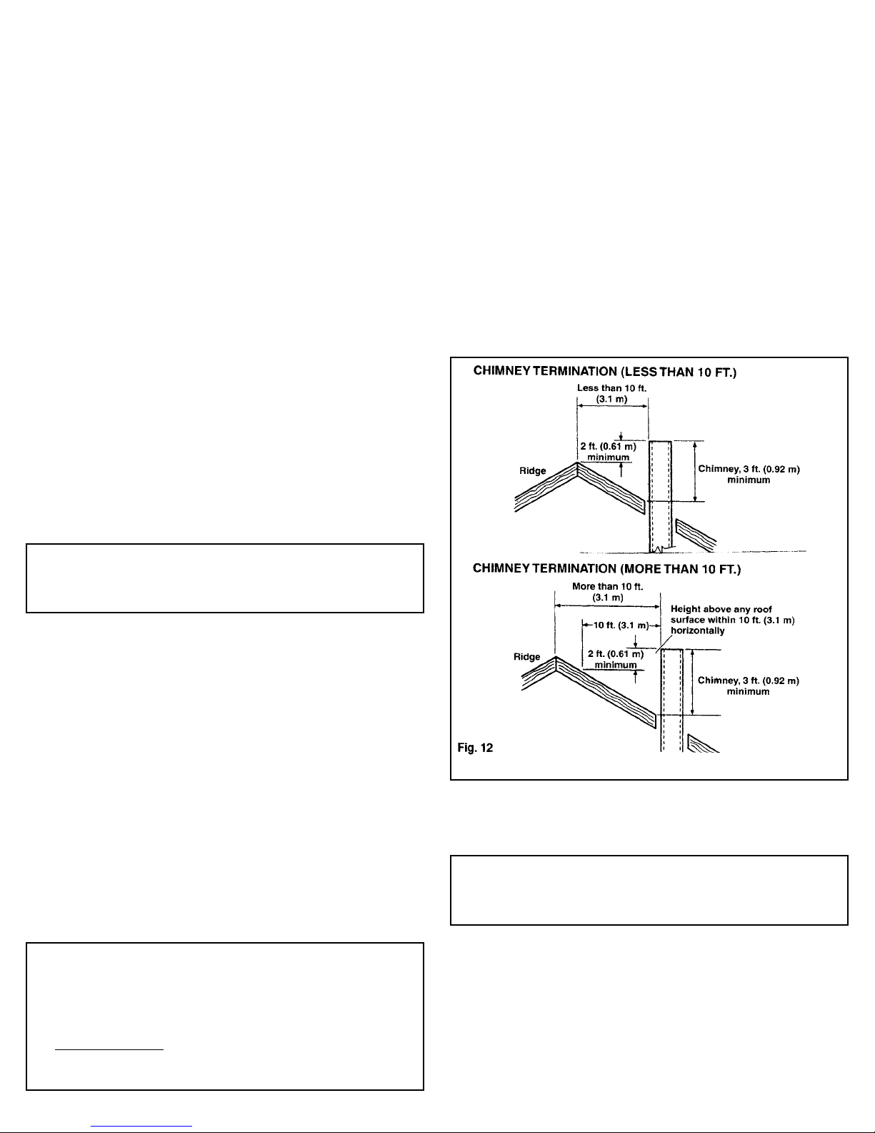
PROPER CHIMNEYS
The National Fire Protection Association (NFPA) requires that all
factory built chimneys be Listed and installed in accordance with
conditions of the Listing in the manufacturers instructions. NFPA
also requires that your chimney extend at least three (3) feet
above the highest point when it passes through the roof and at
least two (2) feet higher than any portion of the building within ten
(10) feet of the chimney.
Factory built chimneys must be what NFPA refers to NFPA
211 1-5.217.4 as Type HT. HT is an abbreviation meaning High
Temperature.
Masonry Chimneys as referred to in NFPA 211 1-5.2.17.6, a field
constructed chimney of solid masonry units, bricks, stones, listed
masonry chimney units, or reinforced concrete that is lined with
suitable chimney flue liners and built with the provisions of Chapter
4 of this standard.
DO NOT CONNECT THIS FURNACE TO A
CHIMNEY SERVING ANOTHER APPLIANCE
WARNING
Return air MUST NOT be drawn from inside the room
where the furnace is located.
FURNACE CASING
1. The furnace is shipped unassembled in a carton attached to
the furnace.
2. Insert the left and right side panels into the slots at the base
of the furnace.
3. Place top panel over the front edge of the furnace and then
into the side panels.
9
MOUNTING THERMOSTAT & SUB-BASE
Thermostat must be mounted on an interiior, centrally located
wall away from direct sunlight and drafts and approximately 5 feet
above the floor.
INSTALLATION
VERTICAL FLUE:
1. Adjustment weight must be in RIGHT HAND SLOT
(marked "V") in bracket on gate.
2. The arrow on flap at bottom of gate must line up with letter
"V" on lower right part of gate. If it does not, remove flap,
turn over and snap onto gate again.
Flap can be removed by inserting small screwdriver at the back
side of the gate between the gate and the flap, then pulling
downward on flap.
HORIZONTAL FLUE:
1. Adjustment weight must be in LEFT HAND SLOT
(marked "H") in bracket on gate.
2. The arrow on flap at bottom of gate must line up with letter
"H" on lower left part of gate. If it does not, remove flap,
turn over and snap onto gate again.
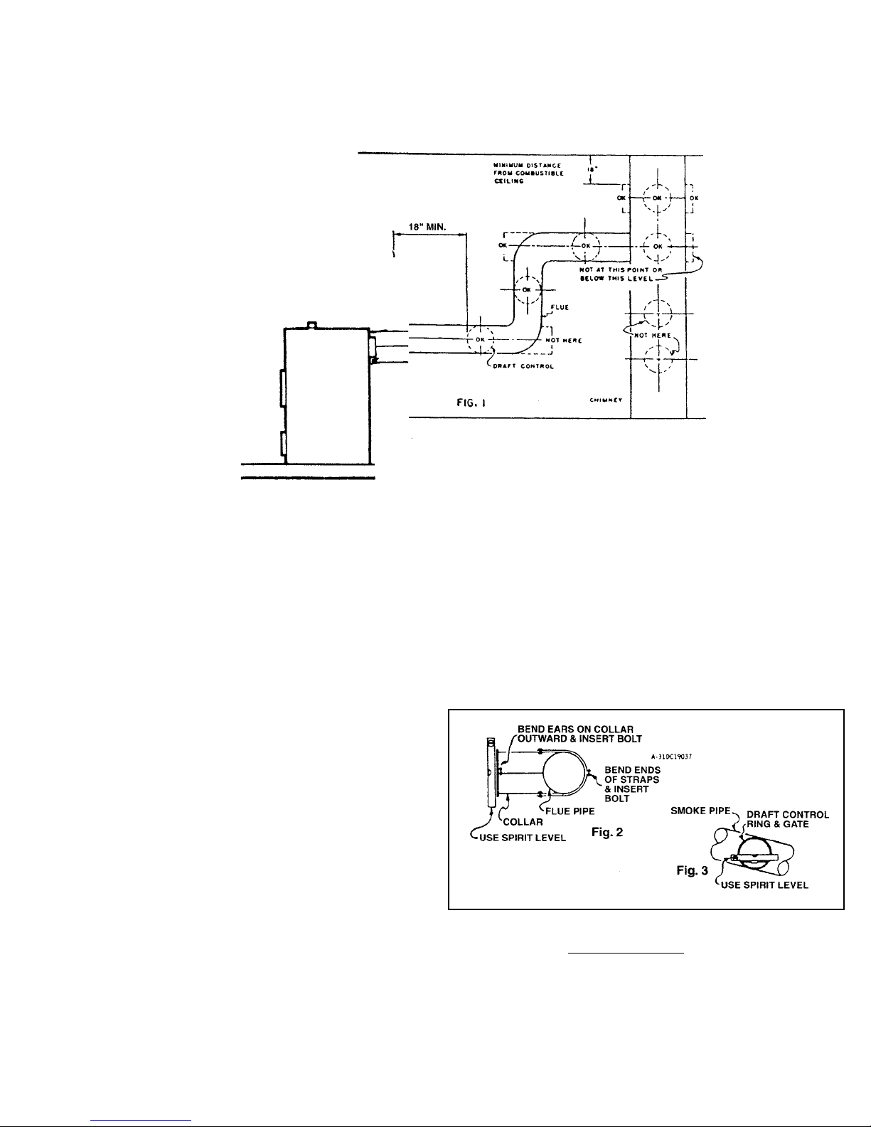
Bend outward the two ears at the front corners of collar and insert
clamping screw. Bolt the remainder of the collar together. See
Figure 2. Hold the collar against the flue in the EXACT position
and mark the outline of the collar on the flue. Cut a hole in the flue
about half an inch smaller than the marks.
Then cut a series of short slits (about 3/8" or 1/2" deep) around
the edges of the opening. After the collar is strapped on the flue
the cut edges can be bent outward into the collar and thus make
a better joint. WHEN FINISHED, THE OPENING INTO THE FLUE
MUST BE EQUAL IN SIZE TO THE COLLAR OF THE DRAFT
CONTROL. If flue pipe is made of material too heavy to bend out
into the collar, the opening into the flue must be within 1/4" of the
same diameter as the collar.
Strap the collar to the flue pipe and place the draft control into the
collar, fastening it there by tightening the clamping screw in the
collar.
Use a spirit level to make sure that the control does not lean for -
ward or backward but instead is plumb in both directions, regard-
less of whether the flue is horizontal, vertical or sloping.
INITIAL SETTING OF BAROMETRIC CONTROL
Set the control at a maximum of .03 or as low a draft as will
give good combustion and meet the requirements for heat. Turn
adjustment weight counter-clockwise to loosen, then slide in slot
to proper position and tighten. Bracket is marked 2, 4, 6, and 8,
which indicates draft settings of .02, .04, etc. (These are drafts in
flue adjacent to control, not over-fire drafts.) A monometer must be
used to accurately adjust flue draft.
INSTRUCTIONS FOR INSTALLING
FIELD R-C
BAROMETRIC DRAFT CONTROLS
CHOOSING THE LOCATION
Do not attach draft control to top or bottom of flue
pipe, nor in a room separated from appliance.
Best location is as close to appliances as possible.
10
Ce manuel convient aux modèles suivants
1
Table des matières
Autres manuels Yukon Eagle Four


