YESOUL E30S Manuel utilisateur

Before using this product,
carefully read
and properly keep this manual.
E30S Product Manual
Product model: E30S
E30S
Elliptical Trainer
YESOUL Smart Elliptical Trainer

Product parameter
Product name
Voltage
Step
Flywheel
Rated maximum load
Net weight
Gross weight
Package size
Dimensions
Standard
YESOUL Smart Elliptical Trainer E30S
12V
40cm
External magnet 6kg
120kg
61.5kg
70kg
(Length) 1450 × (Width) 455 × (Height) 840 (mm)
(Length) 1440 × (Width) 590 × (Height) 1700 (mm)
GB17498.1-2008/GB17498.9-2008
YESOUL Smart Elliptical Trainer E30S

Safety Instructions
1. This device complies with relevant standards of fitness exercise products used at home or for
non-medical purposes.
2. This HB-class sports device is equipped with an electronic speed control. It must not be used
without system control.
3. Avoid using this product at high temperature and humidity or where there is water splashing.
4. Please read the manual carefully before using the product.
5. Keep this device on a fixed flat ground. Select a fixed safe area for exercises. Keep sufficient
clearances (at least 1m) in all directions of this device.
6. Incorrect and irregular training may cause personal injury.
7. The handlebar and other mechanical devices of this product must not be obstructed by the site
during use.
8. Check screws and nuts on a regular basis.
9. The trainer must not be used as a toy or game machine.
10. Installation, use and training instructions are available when you order this product.
11. The owner should inform others of precautions to prevent danger.
12. This device is designed for indoor use. It must be used indoors (not outdoors).
13. Do not transport this device alone.
14. If necessary, please disassemble this product in accordance with the opposite order of
installation steps in the product manual. Please use this product according to its manual.
15. Never close your eyes while using this device.
16. The maximum load-bearing capacity of this device is 120kg.
17. Information about the brake system: Not related to the speed.
18. Training information: Training of the lower and upper limbs and the whole body.
19. Children must not get close to this product without the supervision of an adult.
Consult a doctor before using this product. This is particularly
important for those who are over 35 years old or were once
unhealthy. Before using this product, please read all precau-
tions.

Installation Guide - List of Parts
STEP 1: Check of parts
List of Parts
Hexagon socket head bolt
3/8"-16*70 (17)-2pcs
Hexagon socket head bolt
3/8"-16*95 (19)-2pcs
10#
13#
14#
32/6
32/7
Installation
Before installation, refer to the assembly drawing below, so that you can install this product more
accurately according to the numbers shown below.
S/N Item Quantity
Underframe assembly
Rear bottom tube assembly
Front bottom pipe assembly
Upper column assembly
Left large handle pipe assembly
Right large handle pipe assembly
Left pedal frame assembly
Right pedal frame assembly
Left swing rod assembly
Right swing rod assembly
Rear base cover
Rear cover of shield
Front cover of shield
Pedal
Electronic meter assembly
Electronic meter core assembly
Hexagon socket head bolt
Cross recessed pan head tapping
screws
Hexagon socket head bolt
Hexagon socket head bolt
Hexagon socket head bolt
Locknut
Hexagon socket head bolt
1
1
1
1
1
1
1
1
1
1
1
1
1
2
1
1
2
2
2
2
4
4
8
1
2
3
4
5
6
7
8
9
10
11
12
13
14
15
16
17
18
19
20
21
22
23

1.After unpacking, find the accessories shown below. Keep the following accessories aside. They
will be used in subsequent installation.
STEP 2: Unpacking
Installation Guide
Please pay attention after unpacking! Do not remove other packaging
materials. Please follow the instructions.

Installation Guide
STEP 3: Installation of rear bottom tube assembly and cover
1. Find the rear bottom tube assembly (2), rear base cover (11) and two hexagon socket head (17).
2. First, put a styrofoam pad (A) under the rear end of the underframe (as shown in the figure
below). Then, affix the rear bottom tube assembly (2) under the square tube of the underframe
assembly (1), and alight the holes. Install the two hexagon socket head bolts (17) through the
holes of the square tube of the underframe assembly (1), to lock the rear bottom tube assembly (2)
on the underframe assembly (1).
3. Remove the two cross recessed pan head tapping screws (18) that are locked in advance on the
underframe assembly, and keep them aside. Then put the rear base cover (11) on the square tube
of the underframe assembly (1) and align the holes. Lock the rear base cover (11) on the square
tube of the underframe assembly (1) via the two cross recessed pan head tapping screws (18) (as
shown in the figure below).
Installation tool
Installation Guide
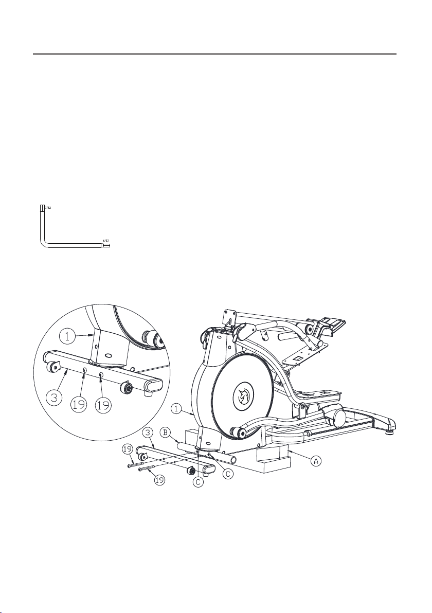
STEP 4: Installation of front bottom tube assembly
1. Find the front bottom tube assembly (3) and 2 hexagon socket head bolts (19).
2. Put one styrofoam pad (A) under the front end of the underframe. Remove the round paper
tube (B) and two hexagon socket head bolts (C) that are locked in advance on the underframe
assembly (1), and keep them aside (they will not be used later).
3. Put the front bottom tube assembly (3) close to the arc-shaped sheet metal on the underframe
assembly (1), and align the holes. Install the two hexagon socket head bolts (19) through the
holes of the front bottom tube assembly (3). Lock the front bottom tube assembly (3) onto the
underframe assembly (1) (as shown in the figure below).
Installation tool

Installation Guide
STEP 5: Installation of the upper column assembly
1. Remove the two hexagon socket head bolts (20) that are locked in advance on the underframe
assembly (1) and keep them aside.
2. Turn the upper column assembly (4) as indicated by the arrow until the sheet metal on the
upper column assembly (4) is close to the mounting sheet metal on the underframe assembly (1)
(never press the signal cable in the column while turning the upper column assembly).
3. Install the two hexagon socket head bolts (20) through the holes of the sheet metal of the upper
column assembly (4), and lock the upper column assembly (4) on the underframe assembly (1) (as
shown in the figure below).
Installation tool

STEP 6: Installation of the left and right handle assembly
Installation Guide
1. Find the left and right handles (5) and (6) (note: The handles are distinguished by “L/R” mark).
2. Remove the four hexagon socket bolts (21) and locknuts (22) that are locked in advance on the
left and right swing rods (9) and (10), and keep them aside.
3. Install the left handle (5) outside the round tube of the left swing rod (9). Then install two
hexagon socket bolts (21) through the holes of the left handle (5) and left swing rod (9). Install the
locknut (22) to secure them (Note: Pay attention to the direction of the locknut (22) (as indicated
below). The hexagon head of the locknut (22) should be aligned with the hexagon hole on the left
handle (5)).
4. Install the right handle assembly (6) on the other side in the same way (as shown in the figure
below).
Installation tool

Installation Guide
STEP 7: Installation of the front and rear covers of shield
1. Find the front and rear covers (12) and (13) of the shield.
2. First, clamp the front and rear covers (12) and (13) securely on the upper column assembly (4) as
indicated by the arrow.
3. Then, pull down the front and rear covers until they are in place outside the left and right shields
of the underframe assembly (1).
4. Insert the left and right dowels of the rear cover (13) of the shield into the square holes of the left
and right shields. Flatten them down (as shown below).
Table des matières
Langues :
Manuels vélo elliptique populaires d'autres marques

Weslo
Weslo Momentum 4.0 Elliptical Manuel d'utilisation et d'entretien

Progear Fitness
Progear Fitness Air elliptical pro 1307 Manuel utilisateur

Torque Fitness
Torque Fitness XPLLP Manuel utilisateur

Octane Fitness
Octane Fitness PRO3700C Manuel utilisateur

Xterra
Xterra FS5.8e Manuel utilisateur

Bodyguard
Bodyguard E-40 Manuel utilisateur

Bonn Germany
Bonn Germany Concept 2.2 Manuel utilisateur

Precor
Precor Resolute RSL 620 Manuel utilisateur

NordicTrack
NordicTrack E 9.2 Elliptical Manuel utilisateur

Vision Fitness
Vision Fitness X6600iNetTV Manuel utilisateur

Matrix
Matrix MX-A5x Manuel utilisateur

SportsArt Fitness
SportsArt Fitness ECO-NATURAL Elite E874 Manuel utilisateur


