XTA DP226 Manuel utilisateur


Page 2 DP224/6 Operators Manual
DP226 Quick Reference
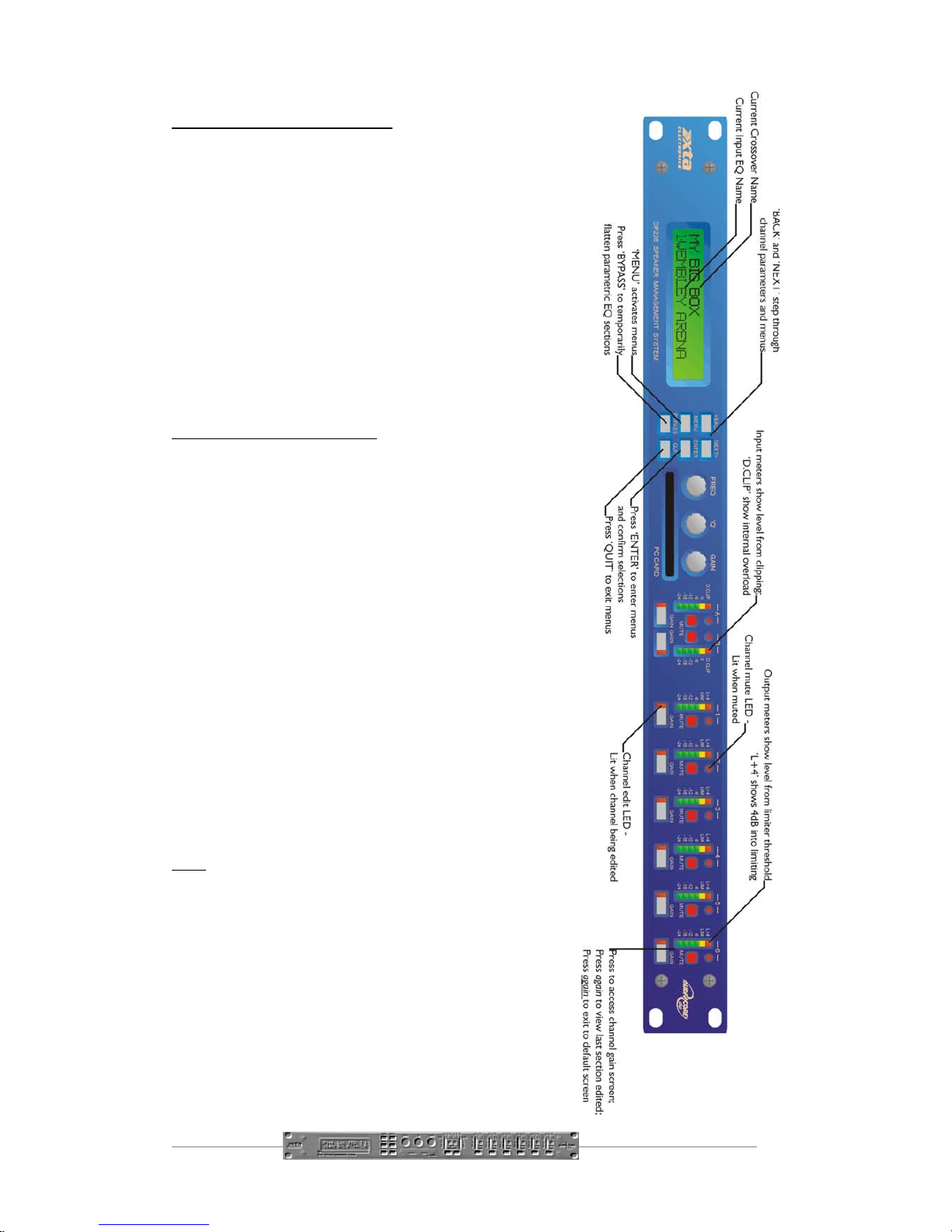
Accessing channels: press channel’s GAIN button.
First press accesses that channel’s gain. To scroll
through a channels parameters, use the BACK and
NEXT keys. Second press accesses last viewed
parameter. Third press will drop back to the default
screen.
Accessing menus: press the MENU key. Use the
BACK and NEXT keys to select the sub-menu
required, and enter using the ENTER key. This applies
to all levels of menu. ENTER always confirms
selections.
The Menus and their Contents
Input Memory Sub-menu: Used for storage and
recall of input EQ, gain and delay. Also used for storage
and recall of complete input memory sets using a PC
card.
Input Setup Sub-menu: Used for ganging input EQ
and globally flattening all input EQ.
X-over Sub-menu: Used for storage and recall of
crossovers, including format, output EQ, output delay,
output gain, and limiter settings. Also used for design of
new crossovers.
Security Sub-menu: Used for locking various
features of the units, using a four digit code.
System Sub-menu: Used to view the units status,
and select various global options such as parametric EQ
‘Q’ or bandwidth units, and output meter monitoring
point (pre or post mute).
Remote GPI Sub-menu: Used to configure the
General Purpose Interface card (if fitted) for remote
recall of memories using contact closure.
Notes
The crossover or output settings are stored and recalled
independently (using store/recall a X-Over) from the input settings
(using store/recall input memory).
The output meters show level, in dB, from the limiter threshold.
The input meters show level, in dB, from input clip.
The high and low-pass filters are defined independently on each
channel.
To access the limiter attack and release parameters, select ‘Auto
Limiter TC’ No, when designing a crossover.
To swap parametric filter units between bandwidth (‘BW’) and ‘Q’,
enter the ‘System sub-menu, select ‘Filter Q or BW’, and select
required readout units.

DP224/6 Operators Manual Page 3
Contents
DP226 Quick Reference 1
The Menus and their Contents 2
Notes 2
Contents 3
Important Safety Information 6
Thanks 7
Unpacking the DP226 7
Introduction 8
Features 8
Front Panel Familiarisation 10
Rear Panel Connections 11
Operating the DP226 12
Note about operation with WindowsTM software. 12
Preliminary Set-up 12
DP226 Configurations 13
Introduction 13
2 x 2 way with Mono Sum 13
2 x 3 way 14
4 way + 2 15
5 way + 1 16
6 way 17
Screen Layouts Overview 18
Audio Function Screens 19
Gain Screen 19
Polarity Screen 20
Delay Screen 21
High and Low Pass Filter Screens 22
Parametric Equaliser Screen 23
Limiter Screen 24

Page 4 DP224/6 Operators Manual
Menu Selection 25
Input Memory Sub-menu 26
Input Memory Recall 26
Input Memory Store 26
Input Memory Store to PC card 26
Input Memory Recall from PC card 26
Input Memory Erase 26
Input Setup Sub-menu 27
Gang Inputs 27
All PEQ’s Flat 27
X-over Sub-Menu 28
Load a Xover 28
Design a Xover 28
Store a Xover 28
Erase a Xover Mem 28
Security Sub-Menu 29
User Specific 29
Xover Only 29
Xover + Trim 29
Xover + Trim + Mute 29
Changes Only 29
Changes + View 29
Changes + Mutes 29
EVERYTHING 29
Entering the Password to Complete the Locking Operation 30
System Sub-Menu 31
System Status 31
LCD Contrast 31
LED Brightness 31
Temperature Alarm 31
Program Update 31
Wake-up Time 31
Output Meters 31
Filter Q or BW 31
Delay Time/Distance 31
Unit Cloning 31
Preset Update 32
Clip Hold Time 32
Interface Sub-Menu 33
Interface Setup 33
Interface Operation 33
Single Unit System 33
Multiple Unit System 34
AES / EBU Sub-Menu 35
Routing Options 35
AES Diagnostics 35
AES / EBU Connections 35

DP224/6 Operators Manual Page 5
Remote GPI Sub-Menu 36
Typical Interface Set-ups 37
RS232 Connection (Single Unit) 37
RS232 Connection (Multiple Units) 37
RS485 Connection 38
Midi Connection 38
Operating Notes 39
Operating Level 39
Grounding 39
Crossover Filter Slopes 40
Time Alignment 40
Output Limiters 41
Setting Accurate Limiter Thresholds 42
Specifications 44
Warranty 45
Options and Accessories 45
Appendices 46
Appendix 1: Limiter threshold in dB to Vrms lookup table. 46
Appendix 2: Default X-over settings and names for all formats. 47
Appendix 3: Equalisation Curves 48
Appendix 4: Frequently Asked Questions 50
Appendix 5: Additional Information: General Purpose Interface 52
Appendix 6: DP224 Crossover Configurations 58

Page 6 DP224/6 Operators Manual
An example of this equipment has been tested and found to comply with
the following European and international Standards for Electromagnetic
Compatibility and Electrical Safety:
Radiated Emissions (EU): EN55013-1 (1996)
RF Immunity (EU): EN55103-2 (1996) RF Immunity, ESD, Burst Transient,
Surge, Dips &Dwells
Electrical Safety (EU): EN60065 (1993)
Important Safety Information
Do not remove Covers.
No user serviceable parts inside, refer servicing to qualified service personnel.
This equipment must be earthed.
CAUTION
RISK OF ELECTRIC SHOCK
DO NOT OPEN
DO NOT EXPOSE TO RAIN OR MOISTURE
ATTENTION
RISQUE DE CHOC ELECTRIQUE
NE PAS ENLEVER
NE PAS EXPOSER A LA PLUIE NI A L’HUMITE
It should not be necessary to remove any protective earth or signal cable shield connections.
Do not defeat the purpose of the polarized or grounding-type plug. A polarized plug has two
blades with one wider than the other. A grounding type plug has two blades and a third
grounding prong. The wider blade and the third prong are provided for your safety. When the
provided plug does not fit into your outlet, consult an electrician for replacement of the obsolete
outlet.
Only use this equipment with an appropriate mains cord.
In the USA the cord should comply with the requirements contained in the Standard for Cord
Sets and Power Supply Cords, UL 817, be marked VW-1, and have an ampacity rating not less
than the marked rating of the apparatus.

DP224/6 Operators Manual Page 7
Thanks
Thank you for choosing the XTA DP226 for your application. Please spend a little
time reading through this manual, so that you obtain the best possible performance
from the unit.
All XTA products are carefully designed and engineered for cutting-edge
performance and world-class reliability. If you would like further information about
this or any other XTA product, please contact us.
We look forward to hearing from you in the near future.
Unpacking the DP226
After unpacking the unit, please check it carefully for any damage. If any is found,
immediately notify the carrier concerned - you, the consignee, must instigate any
claim. Please retain all packaging in case of future re-shipment.

Page 8 DP224/6 Operators Manual
Introduction
The DP226 is a powerful DSP based audio processor, ideally suited for live sound
applications, where it combines the functions of a multitude of conventional products
in a compact 1U unit. To achieve this, the DP226 has two inputs and six outputs
which can be configured in five basic crossover modes – 3 x 2 way; 2 x 3 way; 4 way;
5 way; and 6 way.
Each input has a gain control, variable delay and eight bands of fully parametric
equalisation. Each output has a gain control, variable delay, high and low pass filters,
five bands of fully parametric equalisation, polarity switching and, additionally, a fully
featured limiter.
Remote control is catered for in the form of MIDI, RS232 and RS485 ports, and
multiple user memories are provided for the storage and recall of settings.. Multi-
part security lock-out is available for all controls.
The DP226 is also available with optional AES/EBU digital inputs and outputs.
It has been designed for quick, intuitive adjustment through the use of multiple
controls to provide an easy-to-use interface. Alternatively, it may be controlled
externally by XTA’s proprietary WindowsTM software, along with
existing and future ‘Audiocore’ products.
Features
♦ Superb audio quality – carefully optimised double precision signal processing
coupled with a 40-bit internal data path ensures a dynamic range in excess of
110dB. The high sampling rate means minimal filtering providing exceptional
sonic purity.
♦ A flexible 2-input/6-output multi-mode format caters for any crossover
configuration, regardless of scale.
♦ A total of 46 parametric equalisation bands are available, each providing +15
to –30dB of gain at centre frequencies between 20Hz and 20kHz, with a wide
range of ‘Q’s available between 0.4 to 128. All parameters feature fine
resolution with 1/36 octave frequency steps, 0.1dB gain increments, and 100
‘Q’ settings. Any parametric section can also be set to operate as a high or
low shelving filter.
♦ Each output features a high performance limiter, provided with complete
control over attack, release and threshold parameters. To aid set-up, the
output meters show headroom to the limiter threshold, and use time
constants that track those of the limiter to display precise power usage.

DP224/6 Operators Manual Page 9
♦ Each output features variable high and low pass filters, with a choice of 12, 18
or 24dB/Octave roll-off, and Butterworth, Bessel or Linkwitz-Riley responses.
Independent control of each high and low pass filter allows asymmetric
crossover bands to be created.
♦ Delay of up to 650mS may be independently set for each output, with an
exceptionally fine minimum increment of 2.6µS.
♦ Three velocity-sensitive encoders provide a familiar and intuitive control
format with all filter information displayed simultaneously on a backlit LCD
screen.
♦ The comprehensive standard specification also includes 40 memories, PC
Card storage and remote control via MIDI, RS232 or RS485 ports, with multi-
part security lock-out.
♦ AES/EBU Digital input and output interfaces are available as an option.
♦ Input and output balancing transformers are also available as an option.

Page 10 DP224/6 Operators Manual
Front Panel Familiarisation
LCD Screen : shows menu options,
channel information, and various
parameters as they are adjusted.
Next Key : moves forwards through the list of available parameters.
Back Key : moves back through the list of available parameters.
Menu Key : activates the main menu. A second press selects the last
menu edited. Selection of different menus may be accomplished using
the Back and Next keys, or by turning the ‘Freq’ encoder.
Enter Key : enters the chosen menu and confirms choices.
Bypass Key : bypasses the currently selected parametric EQ section. Note that,
for safety reasons, the high and low pass filters cannot be bypassed using this key.
Quit Key : exits the menu.
Encoders : three velocity sensitive controls allow the
relative parameter displayed on the LCD screen to be
adjusted.
PC Card : PCMCIA card slot allows back-up of input
memory sets, unit cloning data and facilitates the download of
software updates.
Gain Keys : one for each input and output, allowing instant access
to the gain screen for the selected channel. The accompanying LED
illuminates whilst editing is active.
Input Meters : display available headroom below clipping. The
yellow ‘0dB’ LED illuminates at 3dB below the actual clipping point
of the input section. The red ‘D.Clip’ LED shows digital overflow and can therefore
illuminate independently of the rest of the meter.
Output Meters: display headroom below limiting. The yellow
LED illuminates when the limit threshold is reached for that
channel. The red LED indicates 4dB of limiting.
Mute Keys: mutes the appropriate channel, and illuminates the
associated LED.
Autres manuels pour DP226
1
Ce manuel convient aux modèles suivants
1
Table des matières
Autres manuels XTA Équipement d'enregistrement
Manuels Équipement d'enregistrement populaires d'autres marques

Strymon
Strymon NIGHTSKY Manuel utilisateur

Mitsubishi Electric
Mitsubishi Electric 16CH DIGITAL RECORDER DX-TL5000U Manuel utilisateur

Tews Technologies
Tews Technologies TPMC465 Manuel utilisateur

Honeywell
Honeywell Excel 50 Manuel utilisateur

SeaLevel
SeaLevel COMM+8.LPCI Manuel utilisateur

Arturia
Arturia AUDIOFUSE STUDIO Manuel utilisateur