
World Precision Instruments KITE Manuel d'entretien

WORLD
PRECISION
INSTRUMENTS
MANIPULATORS
Care and Maintenance
Serial No._____________________
www.wpiinc.com
INSTRUCTION MANUAL
082620


Manipulators
World Precision Instruments i
Copyright © 2015 by World Precision Instruments, Inc. All rights reserved. No part of this publication
may be reproduced or translated into any language, in any form, without prior written permission of
World Precision Instruments, Inc.
CONTENTS
ABOUT THIS MANUAL ................................................................................................................... 1
INTRODUCTION .............................................................................................................................. 1
Notes and Warnings................................................................................................................. 1
INSTALLING THE TILT BASE.......................................................................................................... 2
ADJUSTING THE ANTI-DRIFT TENSION ON MICROMANIPULATORS .................................. 2
Adjusting the X Coarse Axis Drift........................................................................................... 3
Adjusting the Y-Axis Drift......................................................................................................... 6
Adjusting the Z Axis Drift......................................................................................................... 7
ACCESSORIES................................................................................................................................... 9
Manipulators.............................................................................................................................. 9
Optional Accessories................................................................................................................ 9
SPECIFICATIONS.............................................................................................................................. 9
KITE............................................................................................................................................... 9
M3301........................................................................................................................................10
MD4R .........................................................................................................................................10
MMJ.............................................................................................................................................10
WARRANTY .....................................................................................................................................11
Claims and Returns ................................................................................................................11
Repairs.......................................................................................................................................11

ii World Precision Instruments

Manipulators
World Precision Instruments 1
ABOUT THIS MANUAL
The following symbols are used in this guide:
This symbol indicates a CAUTION. Cautions warn against actions that can cause
damage to equipment. Please read these carefully.
This symbol indicates a WARNING. Warnings alert you to actions that can cause
personal injury or pose a physical threat. Please read these carefully.
NOTES and TIPS contain helpful information.
INTRODUCTION
Your micromanipulator is a precision instrument. It has been calibrated at the factory
and is ready for use. As with any delicate mechanical device, it needs your care and
attention for long term accurate performance. The following are some helpful hints to
make this possible.
Notes and Warnings
CAUTION: When handling a micromanipulator, set it down gently. Dropping it
(even a short distance) can be damaging to the general alignment and
adjustment.
CAUTION: When not in use, adjust the three (X-Y-Z) guide surfaces in such a
way that they are not exposed and cover the manipulator with a plastic bag.
Dirt is your biggest enemy.
CAUTION: If the manipulator is not in use for a prolonged time, occasionally
work the three surfaces repeatedly back and forth to keep the grease pliable.
Never oil the guide surfaces and under normal use you should not have to
apply grease for many years.
CAUTION: When using the motorized version always be sure to check that the
edge of the micrometer is aligned with the red dots on the motor housing in
each axis before using the manual control for coarse positioning. Running the
motorized axes repeatedly against either end limit can damage the motor. Be advised
that this damage is not covered by any warranty.
CAUTION: When using the dual tool holder micromanipulators, Models MD4R
and MD4L, be careful not to twist the revolving, spring-loaded axes too hard or
too far. This may damage the spring.

2 World Precision Instruments
INSTALLING THE TILT BASE
Fig. 1 (Left) M3 Tilting Base.
Fig. 2 (Right) The M3301 is installed on an M3 Tilting Base with an optional 5 lb. weight
(WPI# 5464).
To install the M3 Tilting Base, remove the ring clamp by removing the two screws with
the Allen wrench provided. Attach the manipulator to the tilting base by using the two
screws provided with the M3. Only two screws are required, because two holes are
used with a right-handed manipulator, and the other two holes in the tilting base are
used for the left-handed version.
ADJUSTING THE ANTI-DRIFT TENSION ON
MICROMANIPULATORS
Fig. 2 shows a side view of the M3301L manual micromanipulator. Depending on the
angle of application and the weight carried on any one guide-way, you may experience
some drift. This can be easily corrected. Follow the procedure on the following pages
to tighten the drag on the coarse manual slides.
In this manual, you can see how to adjust the anti-drift tension on the M3301, but
the procedure is similar for the DC3001R, DC3001L, MD4R, MD4L, KITE-L, KITE-R,
MMJR and MMJL. A micromanipulator axis may begin to move gradually under its own
weight even if it’s not being touched. This phenomenon is referred to as mechanical
drift. It occurs from normal use of the of the manipulator axes over time. Each coarse
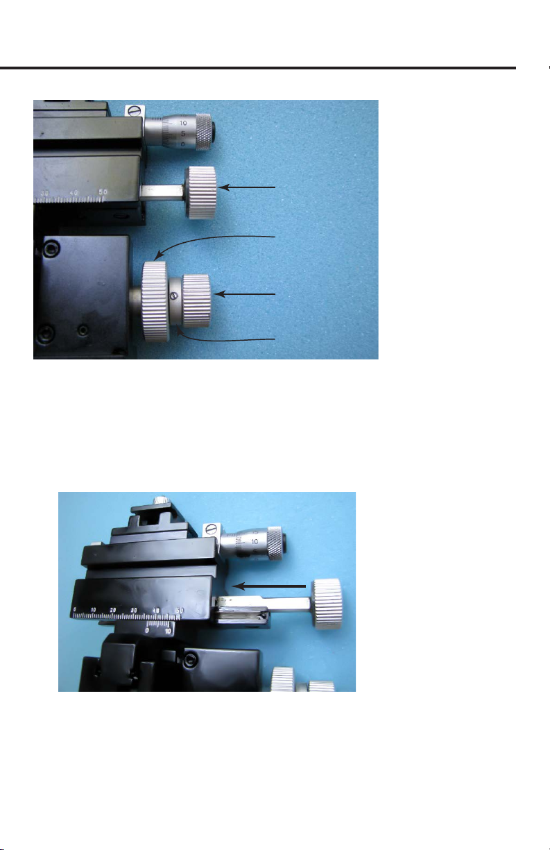
axis control (shown below) of the micromanipulator has its own separate adjustment
to counteract drift. What follows is the basic procedure to eliminate drift in each of the
axes through adjustment of the anti-drift tension.
Manipulators
World Precision Instruments 3
X-Axis Coarse
Adjustment Knob
Z-Axis Coarse
Adjustment Knob
Y-Axis Coarse
Adjustment Knob
Adjustment Ring
Adjusting the X Coarse Axis Drift
1. TherststepistorotatetheX-AxisCoarseAdjustmentknobclockwiseuntilthex-
axis reaches the end of its travel in the fully extended position as indicated by the
black arrow in Fig. 3. This is necessary, because it provides better access to the
knob. In step 2, you will use a pair of pliers to secure this knob while loosening
the black locking nut so that the adjustment can be made.
Fig. 3 Fully extend the X-axis away from adjustment knob.

4 World Precision Instruments
2. If you have an M3301, use the hex key provided and loosen the set screw in the
X-Axis Coarse Adjustment knob (Fig. 4). For a KITE, see below.
Fig. 4 Loosen the set screw on the M3301.
If you have a KITE, use a pair of pliers to secure the X-Axis Coarse Adjustment
knob to prevent it from rotating (Fig. 5). Don’t grab the knob with the pliers
directly, because the jaws will cut into the aluminum knob. Instead, take a piece
of paper and fold it about ½“ wide over upon itself 5 or 6 times to make it thicker.
Then, wrap it around the knob to protect the knob.
0.5” wide paper
folded over
several times
Fig. 5 Wrap the knob with a thick layer of papers so the pliers do not gouge the
aluminum knob.
3. If you are right-handed, hold the pliers in your left hand. With your right hand
insert the special tool (WPI# 502105) (Fig. 6) into the black slot on the end of the
knob. Prevent the silver knob from turning, and rotate the tool counter-clockwise
to unscrew the black locking nut (Fig. 7).

Manipulators
World Precision Instruments 5
Hold knob and turn
screw counter-
clockwise.
Fig. 6 (Left) 502105 Manipulator Adjustment Tool
Fig. 7 (Right) The outer ring of the knob remains stationary, while you turn the inner
screw counter-clockwise.
4. Once the black locking nut is loose, the silver knob can be freely tightened or loos-
ened to adjust the amount of resistance to drift. To prevent the axis from moving
while making the tension adjustment, use your left hand to hold the body of the
axis securely while adjusting the silver knob (clockwise to increase tension) with
your right hand. At some point you will feel the resistance of the knob increase
as it begins to compress against the spring steel and nylon friction components.
Adjustment is somewhat arbitrary. When the amount of tension feels about right,
use the 502105 tool to re-tighten the black locking nut to secure the adjustment.
Then, test the anti-drift tension.
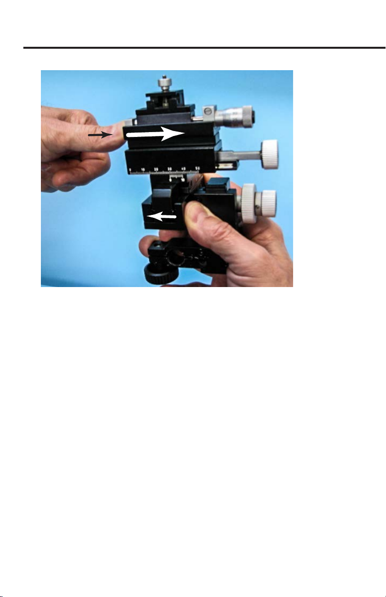
5. Test the drift resistance of the axis by pushing on it with your hand to see how
easily it moves. A good technique for doing this is to push on the axis body with
your left thumb while providing a counteracting force on the lower part of ma-
nipulator using your right hand (Fig. 8). When the tension is adjusted correctly, it
will not be easy to move the axis by pushing it.
6 World Precision Instruments
Apply mechanical
pressure on the X-
axis with left hand
thumb to test for
drift resistance.
Fig. 8 To test the drift resistance, press on the x-axis. It should not move easily.
NOTE: The correct amount of drift resistance depends upon the working orientation
of the manipulator, the load on the axis, and personal preference.
6. If the action feels too tight or too loose, unscrew the black locking nut again and
re-adjust the tension accordingly. It may be necessary to repeat this procedure
several times. Typically, the goal is to get the tension just tight enough to prevent
the axis from drifting under its own weight (while loaded), but not any tighter than
necessary to achieve this end. The correct amount of tension often occurs within
a narrow range of adjustment. If you make it too tight, the knob will be harder
than necessary to turn and the friction components will wear faster. This proce-
dure requires patience!
Adjusting the Y-Axis Drift
The adjustment of the Y-axis tension is performed with essentially the same
techniques as that described for the X coarse axis. The Y-axis is controlled by the
Y-Axis Coarse Adjustment knob shown in Fig. 9.
If the manipulator is operated in standard position (with the electrode clamp located
above the manipulator body as shown in Fig. 2, then the Y-axis does not typically have
a tendency to drift unless the manipulator body is tilted to the left or right relative to
the vertical plane passing parallel through the X-axis.
Ce manuel convient aux modèles suivants
3
Table des matières
Autres manuels World Precision Instruments Équipement de laboratoire

Manuels Équipement de laboratoire populaires d'autres marques


Agilent Technologies
Agilent Technologies 5800 ICP-OES Manuel utilisateur

Endress+Hauser
Endress+Hauser Cleanfit CPA875 Manuel utilisateur

NI
NI PXI-5422 Manuel

Collomix
Collomix Aqix Manuel utilisateur

SPEX SamplePrep
SPEX SamplePrep 6875 Freezer/Mill Series Manuel utilisateur

Ocean Insight
Ocean Insight FLAME-NIR+ Manuel utilisateur


