woodmizer SLR Mode d’emploi

WARNING! Read and understand this
manual before using this machine.
!
Shingle/Lap Sider
Safety, Operation, Maintenance, &
Parts Manual
SLR rev. A.00 - G.00
Safety is our #1 concern!
March 1997
Form #903
For use with LT15* through LT70 models.
*LT15 requires an adapter kit.

Active Patents assigned to Wood-Mizer, LLC
Belzile, Luc. 2016. Portable saw mill with bed adjustments. US Patent US 9,352,480B, filed Sepember 11, 2012, and
issued May 31, 2016.
Belzile, Luc. 2019. Blade sharpening and setting system. US Patent US10315260B2, filed August 27, 206, and issued
June 11. 2019.
Vogel, Chris. 2020. Wood cutting band saw blade having reduced kerf dust. US Patent US10625353B2, filed January 9,
2015, and issued June 21, 2020.
Bedel, Ambrose. 2011. Pallet dismantler. US Patent US 2011/0138984 A1, filed December 15, 2009, and issued June 16,
2011.
Laskowski, Jeff. 2006. Articulating deck mower with deck height adjuster. US Patent US 7,089,722 B2, filed September
30, 2004, and issued August 15, 2006.
Latuszek, Scott R., Dufek, Scott A. and Kohrman, Mark J. 2010. Latch for a pivoting mower deck. US Patent US
2010/0212278 A1, filed May 12, 2008, and issued August 26, 2010.
©2020 Wood-Mizer LLC
Printed in the United States of America, all rights reserved. No part of this manual may be reproduced in any form by any
photographic, electronic, mechanical or other means or used in any information storage and retrieval system without
written permission from
Wood-Mizer, LLC
8180 West 10th Street
Indianapolis, Indiana 46214
&DOLIRUQLD
3URSRVLWLRQ:DUQLQJ
:$51,1*%UHDWKLQJJDVGLHVHOHQJLQHH[KDXVWH[SRVHV\RXWRFKHPLFDOVNQRZQWR
WKH6WDWHRI&DOLIRUQLDWRFDXVHFDQFHUDQGELUWKGHIHFWVRURWKHUUHSURGXFWLYHKDUP
$OZD\VVWDUWDQGRSHUDWHWKHHQJLQHLQDZHOOYHQWLODWHGDUHD
,ILQDQHQFORVHGDUHDYHQWWKHH[KDXVWWRWKHRXWVLGH
'RQRWPRGLI\RUWDPSHUZLWKWKHH[KDXVWV\VWHP
'RQRWLGOHWKHHQJLQHH[FHSWDVQHFHVVDU\
)RUPRUHLQIRUPDWLRQJRWRZZZ3ZDUQLQJVFDJRY
:$51,1*'ULOOLQJVDZLQJVDQGLQJRUPDFKLQLQJZRRGSURGXFWVFDQH[SRVH\RXWR
ZRRGGXVWDVXEVWDQFHNQRZQWRWKH6WDWHRI&DOLIRUQLDWRFDXVHFDQFHU$YRLGLQKDOLQJ
ZRRGGXVWRUXVHDGXVWPDVNRURWKHUVDIHJXDUGVIRUSHUVRQDOSURWHFWLRQ
)RUPRUHLQIRUPDWLRQJRWRZZZ3:DUQLQJVFDJRYZRRG

Table of Contents Section-Page
Table of Contents WM doc 9/10/20 iii
SECTION 1 INTRODUCTION
1.1 Safety Symbols ...................................................................................... 1-1
SECTION 2 INSTALLATION
2.1 Assembly................................................................................................ 2-1
2.2 Installation and Setup............................................................................. 2-3
2.3 Installation and Setup (revision A.00 through F1.01)............................ 2-4
SECTION 3 LT15 INSTALLATION
3.1 LT15 Rev. E6.04+.................................................................................. 3-1
3.2 LT15 Rev. E4.00 - E6.03 ....................................................................... 3-3
3.3 LT15 Rev. A0.00 - E3.03....................................................................... 3-4
SECTION 4 SHINGLE OPERATION
4.1 Shingle setup .......................................................................................... 4-1
4.2 Shingle cutting operation ....................................................................... 4-4
SECTION 5 LAP SIDING OPERATION
5.1 Lap siding setup ..................................................................................... 5-1
SECTION 6 REPLACEMENT PARTS
6.1 Frame 1 ................................................................................................ 6-1
6.2 Frame 2 ................................................................................................ 6-3
6.3 Frame 3 .............................................................................................. 6-4
6.4 LT15 Adapters .................................................................................... 6-5
6.5 LT15 Auxiliary Bed Rail ....................................................................... 6-6
6.6 Shingle Lap Siding Resaw (revision A.00-F.01) ................................... 6-7
Introduction
Safety Symbols
1
1-1 WM doc 9/10/20 Introduction
SECTION 1 INTRODUCTION
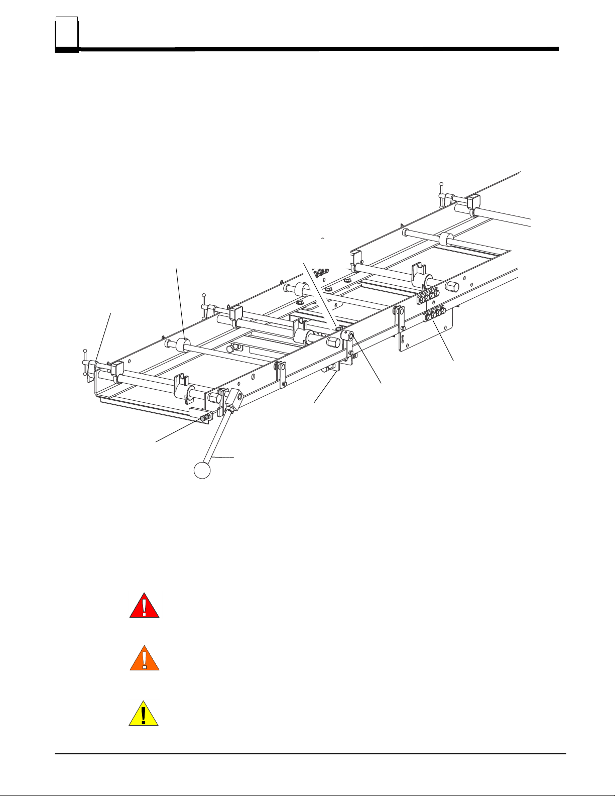
The Shingle/Lap Siding Option (SLR) (see FIG. 1-1) creates tapered shingles or siding with your
Wood-Mizer sawmill.
1.1 Safety Symbols
The following symbols and signal words call your attention to instructions concerning your per-
sonal safety. Be sure to observe and follow these instructions.
DANGER! indicates an imminently hazardous situation which, if not avoided,
will result in serious injury or death.
WARNING! suggests a potentially hazardous situation which, if not avoided,
could result in serious injury or death.
CAUTION! refers to potentially hazardous situations which, if not avoided,
may result in minor or moderate injury or damage to equipment.
FIG. 1-1 MAJOR COMPONENTS
TDSLR02-01
Siding Lift Roller
Shingle Cam
Link Joint
Clamp Assembly
Bed Rail Mount
Shingle Taper
Adjustment Bolt
Siding Taper
Adjustment Bolt
Shift handle
Introduction
Safety Symbols 1
Introduction WM doc 9/10/20 1-2
NOTICE indicates vital information.
WARNING! Clean sawdust from all areas where sawdust may
gather after every 8-hour shift. Failure to do so may result in fire,
causing death or serious injury.
SETUP SAFETY
WARNING! Do not use if the mill is set up on ground with more than a 10
degree incline. An incline could cause the mill to tip over.
Use a lifting device (fork lift, crane, etc.) for parts over 100 lbs.
Use two persons for lifting parts over 50lbs.1
Keep all non-essential personnel out of the area while setting
up the equipment.
1.For more information on lifting safety see NOISH Lifting Equation athttps://www.cdc.gov/niosh/docs/94‐110/

Installation
Assembly
2
2-1 WM doc 9/10/20 Installation
SECTION 2 INSTALLATION
WARNING! Turn the base unit’s power to OFF, remove the key, and discon-
nect the battery ground terminal, if applicable.
On electric equipment, lock out power supply before performing any installa-
tion. See Electrical Lockout Procedures (OSHA regulation 1910.147, appendix
A reprinted in the Operator’s Manual).
Ensure your unit is on a level surface and secure from movement.
2.1 Assembly
1. Uncrate the SLR; discard the shipping braces (total 8) and fasteners. See FIG. 2-1.
FIG. 2-1
Part Part number Qty
Plate, SLR Link Arm Joint 128328 6
SLR Fastener Kit 130832 1
Fastener box contains: Bolt, 3/8-16x1 Gr5 HH F05007-87 32
Washer, 3/8 Flat SAE F05011-3 40
Nut, 3/8-16 Flanged Nylock F05010-222 32
Washer, 3/8 Split Lock F05011-4 8
Bolt, 3/8-16x3/4 Gr5 F05007-118 8
TDSLR01-01
Handle shipping position
Shipping braces
Mounting brace plates
Disassemble but DO NOT DISCARD

Installation
Assembly 2
Installation WM doc 9/10/20 2-2
2. Lay out the frames as shown in FIG.2-2 to attach plates as shown in FIGs. 2-2 and 2-3
FIG. 2-2
FIG. 2-3
TDSLR02-12
Bolt, 3/8-16x1 Gr5
3/8 Flat washer
Brace plate
Nut, 3/8-16 Flanged Nylock
NOTE: If attaching the SLR to an LT15, use
the brace plates from the LT15 Adapter kit
See SECTION 3 LT15 Installation
TDSLR02-13
Link plate
3/8 Flat washer
3/8 Lock washer
Bolt, 3/8-16x3/4 Gr5
Nut, 3/8-16 Flanged Nylock
Link plate
3/8 Flat washer
Bolt, 3/8-16x1 Gr5
Screw in shift handle
NOTE: If attaching the SLR to an LT15, see SECTION 3
LT15 Installation for handle placement

Installation
Installation and Setup
2
2-3 WM doc 9/10/20 Installation
2.2 Installation and Setup
WARNING! Use a lifting device (fork lift, crane, etc.) for parts
over 100 lbs.
Use two persons for lifting parts over 50lbs.1
1. Position the sawhead upward, out of the way.
2. Lower all log supports.
3. Move front pivoting bed rail parallel to the bed frame.
4. Position the SLR on the mill bed with the mounting brackets around the front and rear bed rails.
a. Position the shift handle at the front end of the mill.
b. Ensure the SLR frame is lying flat on the bed rails.
NOTICE: DO NOT tighten the clamp bolts on the bed rails. The SLR bed
must be able to move during operation. The clamp bolts should only be tight-
ened before towing the sawmill with the SLR attached.
5. Slide the SLR frame all the way over toward the inboard side of the sawmill bed until the SLR
stops touch the bed rail stop blocks.
1.For more information on lifting safety see NOISH Lifting Equation athttps://www.cdc.gov/niosh/docs/94‐110/
FIG. 2-4
TDSLR02-02
Shift handle
towards the front
SLR stop against
board stop block
Log supports down
Front bed rail out
of the way
Installation 2
Installation
2.3 Installation and Setup (revision A.00 through F1.01)
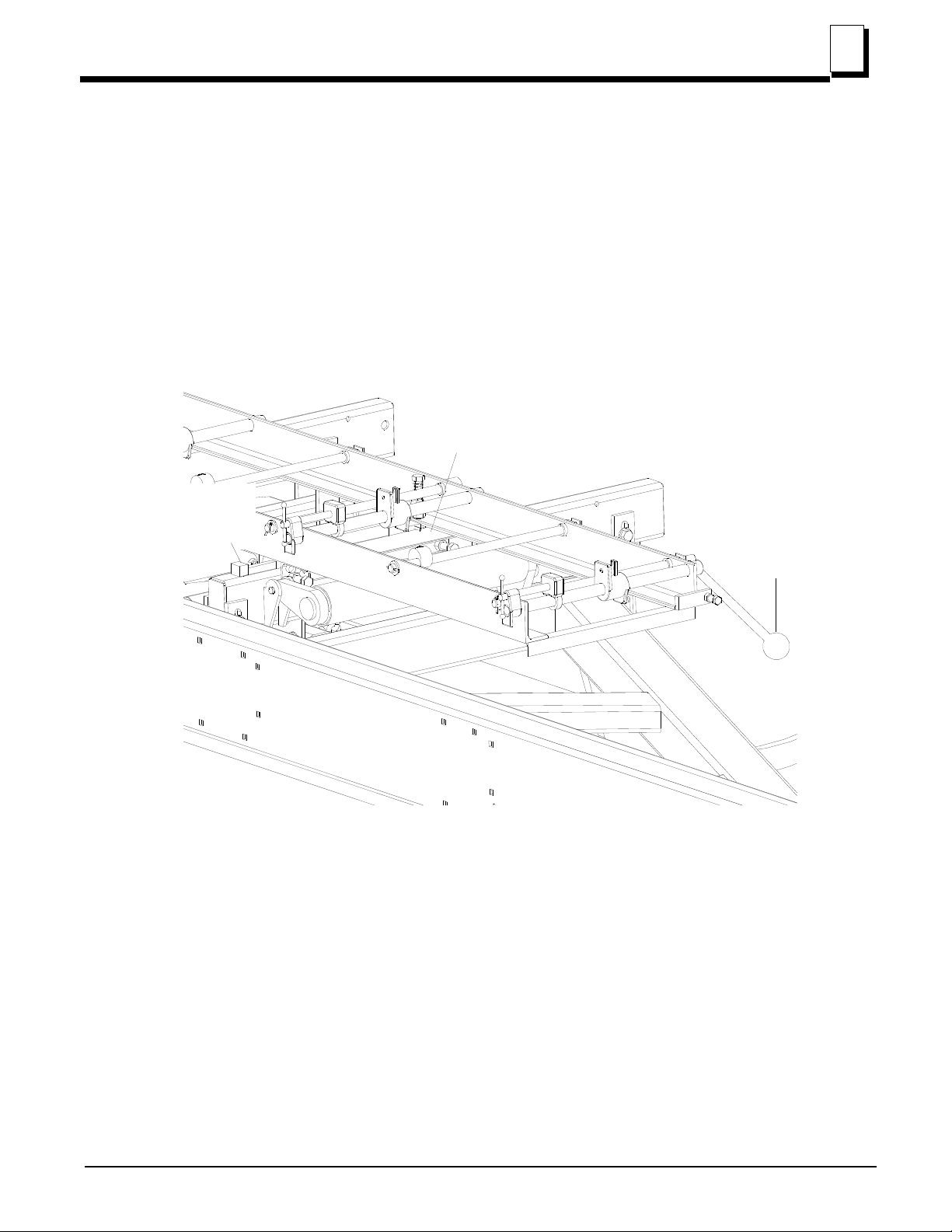
1. Position the SLR on the mill bed with the mounting brackets around the front and rear bed rails.
The shift lever should be at the front end of the mill. Make sure the SLR frame is lying flat on the
bed rails. DO NOT tighten the clamp bolts on the bed rails. The clamp bolts should only be tight-
ened before towing the sawmill with the SLR attached.
2. Slide the SLR frame all the way over toward the inboard side of the sawmill bed until the SLR
stops touch the bed rail stop blocks.
FIG. 2-5
SLR stop
against
bed rail stop
Mounting brackets
positioned on bed rails
Shift lever
toward front
of sawmill
SM0091B

LT15 Installation
LT15 Rev. E6.04+
3
3-1 WM doc 9/10/20 LT15 Installation
SECTION 3 LT15 INSTALLATION
WARNING! Turn the base unit’s power to OFF, remove the key, and discon-
nect the battery ground terminal, if applicable.
On electric equipment, lock out power supply before performing any installa-
tion. See Electrical Lockout Procedures (OSHA regulation 1910.147, appendix
A reprinted in the Operator’s Manual).
Ensure your unit is on a level surface and secure from movement.
3.1 LT15 Rev. E6.04+
(Bed Sections Rev. G.00+): Kit SLRKIT-LT15.1 is required to mount the SLR.
1. Place the rail adapter on the second and third bed rails of the first bed section as shown in FIG.
3-1.
2. Slide the adapter against the bed rail stop blocks.
NOTE: If the adapter contacts the log support first, raise the support to the
height of the adapter and use the log support as the side starting point.
FIG. 3-1
TDSLR03-02
Front of bed
Board stop
Log support
Board stop
Brace to front
Autres manuels pour SLR
1
Table des matières
Autres manuels woodmizer Matériel de construction


