WoodMaxx WM Series Manuel utilisateur

TABLE OF CONTENTS
All content in this manual; pictures, and text are the sole property of
WoodMaxx™ Power Equipment Ltd. © 2014 No unauthorized reproduction.
TABLE OF CONTENTS

CONGRATULATIONS! You have just purchased the WoodMaxx™ WM-Series
Wood Chipper, the strongest, safest and the most compact PTO wood chip-
per available. We have compiled this owner’s manual to help you under-
stand and appreciate your chipper. By taking a few minutes to read this
manual and understand the maintenance instructions, it will give you better
performance and extend the life of your chipper. Read the manual before
operating the chipper.
INTRODUCTION
1
SET-UP INSTRUCTIONS
Your chipper does need to be set up prior to installation. It arrives in a steel
crate that can be dismantled in minutes.
See Assembly Instructions
The in-feed bin and discharge chute are shipped with the unit and are locat-
ed in the bottom of the steel crate.
Visually inspect the in-feed bin, and the fly wheel before attaching to
tractor, and applying power to ensure that nothing is in the chipper head. If
the chipper deflector or any of the guards have been removed for shipping,
be sure to replace them properly before use.
The PTO (Drive-Line) is also shipped with the unit and is located in the bot-
tom of the steel crate.
When mounting, keep the chipper as close to the tractor as possible.
Make sure that the PTO shaft will not bottom out in the shortest position.
While in use, keep the PTO shaft straight. No more than 15 degrees from
level is acceptable.
Do not operate the chipper without the chip deflector properly in place.
Read and understand all assembly instructions prior to assembly.

ASSEMBLY INSTRUCTIONS
2
Before you get started, there are a few tools you will need:
Assembly Time 2.5 Hours
Remove the plastic wrapping from the crate and inspect the chipper for any
obvious shipping damage.
Remove and unwrap all the chipper components that are packaged in the
crate.
Remove the cardboard box from
the in-feed bin. This box contains
the user’s manual, hardware pack-
et, extra shear bolts, and any ad-
ditional item that you may have
purchased such as extra chipper
knives. [Fig. 1a]
Open the hardware packet and organize the enclosed fasteners into sepa-
rate piles. There is a picture of the hardware on pg. 4 of this manual that you
can use as a guide to ensure that you use the correct hardware in the up-
coming steps.
Remove the four bolts that secure the top of the crate frame. Remove the top
of the crate, and set it aside.
Located on the bottom of the crate
is a cross bar that secures the chip-
per to the frame. Loosen the two
bolts that hold this bar in place, and
drive the bar forward with a dead
blow hammer. [Fig. 1b].
Fig. 1a
Fig. 1b
• 13mm Wrench (same as 1/2”)
• 16mm Wrench (same as 5/8)
• Adjustable Wrench
• 3/16 Allen Wrench
• 6mm Allen Wrench

ASSEMBLY INSTRUCTIONS
3
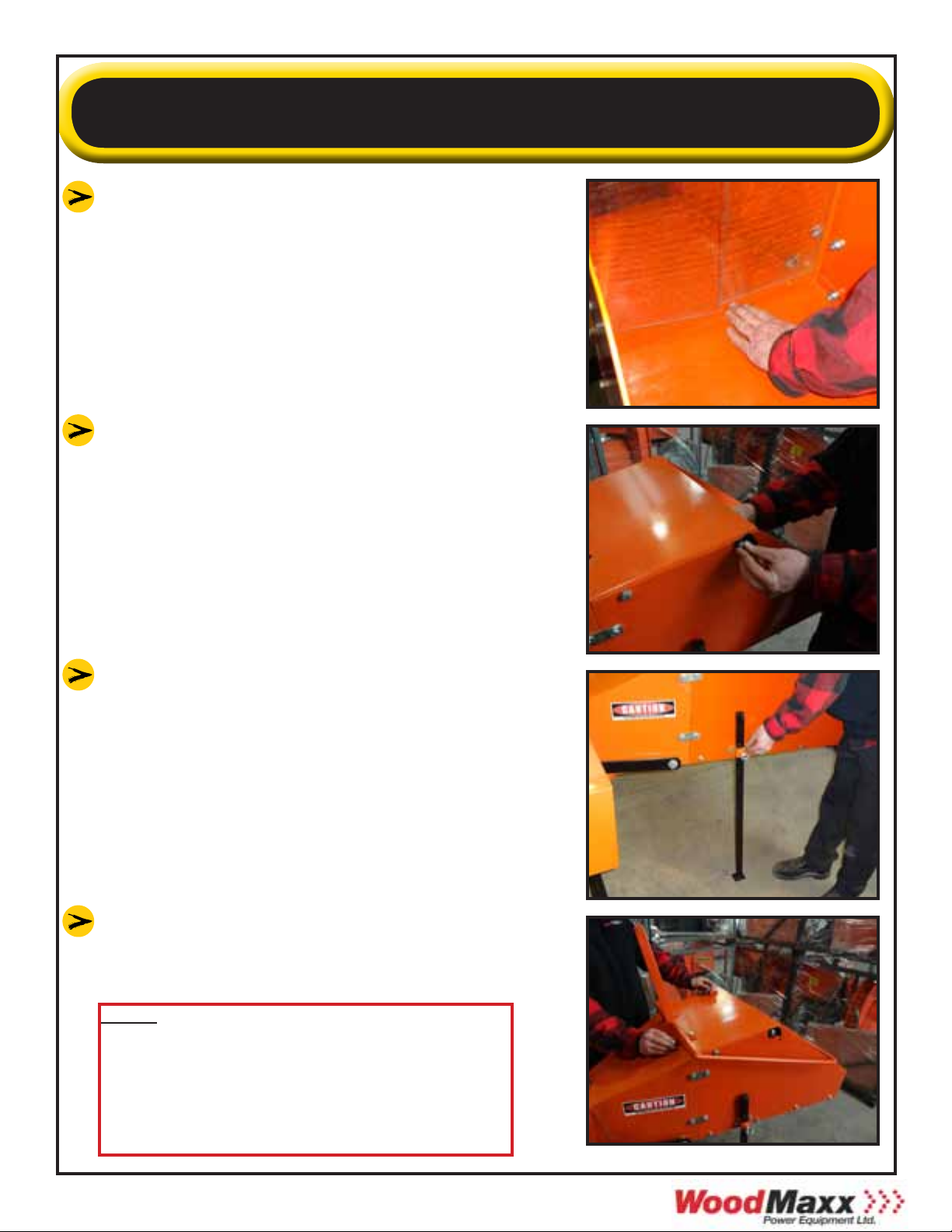
Locate the lift point on the top of the chipper. This is the balance point, and
the only point the chipper should be lifted from.
Using a chain or strap that is rated
strong enough to lift the weight of
the chipper, lift the chipper out of the
crate. [Fig. 2]
If you do not have a front end loader,
attach the three point hitch of your
tractor to the chipper to lift the chip-
per out of the crate.
Measure the distance from the PTO
spline of your tractor to the ground
[Fig. 3]. Write down this measure-
ment here ________. You will need it
for the next step.
While the chipper is raised in the air,
attach the four adjustable base legs
so that when the chipper is on the
ground, the spline of the chipper is
slightly lower than the spline of your
tractor. [Fig. 4]. The shaft does not
need to be perfectly horizontal, but it
is recommended that the slope of the
PTO shaft is no more than 15 degrees.
[Fig. 5]
Fig. 2
Fig. 3
Fig. 4 Fig. 5
15°
At this time, carefully lower the chipper to the ground, and remove the
chain or strap

ASSEMBLY INSTRUCTIONS
4
In-feed bin left
side panel
In-feed roller
assist lever
Hardware box
& accessories
Support leg
In-feed bin
right side
panel
In-feed bin
bottom panel
In-feed bin
top panel
Adjustable
base legs
Discharge
chute
(2) CAT 1 Draw
Pins
(5) Clevis Pins
(1) Spring
Removal Tool
(1) 5/8”x4” Pin
(2) 1/2”x4”
Pins
(38) 10mm
Washers
(20)M10x-
25mm
(4)M10x15
(20)M10 Lock
Nuts
(4) Lock
Washers
(8) Fender
Washers
(4) 2-Hole
Straps

ASSEMBLY INSTRUCTIONS
5
Outside mount
(bolt, fender washer)
Inside mount
(washer, lock nut)
Attach the left panel of the in-feed bin us-
ing two of the 2-hole straps and two M10x-
25mm bolts. Straps will bend when tight-
ened down. This panel can be identified by
the two small holes on the bottom of the
panel where the fasteners for the support
leg attach. [Fig. 6]
Attach the right side panel in the same
manor. [Fig. 7]
Attach the bottom panel of the in-feed bin,
by first inserting the two M10x25 bolts
through the side panels in the two holes
closest to the feed roller. Do not tighten
these bolts yet, and allow the panel to hang
vertically. [Fig. 8]
Raise the bottom panel in place and insert
the two M10x25 bolts the side panel in the
two holes closest to the end of the panel.
[Fig. 9]
Install the remaining four M10x25 bolts in
the remaining four holes in the lower panel.
[Above] View of proper assembly of in-feed
bin using 2 hole straps. All other bolts are
typically assembled as follows; bolt- washer-
panel-washer-lock-nut
Fig. 6
Fig. 7
Fig. 8
Fig. 9
Use Fender
Washers Here
ASSEMBLY INSTRUCTIONS
6
Before tightening the bolts, ensure that
the lower panel is slightly higher than
the in-feed bin. This will prevent mate-
rial from hanging up where the two
pieces join together. [Fig. 10]
Attach the top panel of the in-feed bin
by installing the four M10x25mm bolts
in the two forward holes of the panel.
Affix the safety bar stop to the top left
of the in-feed bin. [Fig. 11].
Attach the support leg with two
M10x25 bolts. [Fig. 12]. Remember, the
support leg should be in the down po-
sition during storage only. When the
chipper is attached to the tractor, the
support leg should be in the up position
at all times.
Attach the upper feed roller assist lever
using four M10x25mm bolts. [Fig. 13].
Fig. 10
Fig. 11
Fig. 12
Fig. 13
Note: Although we choose to install
the hardware with the bolts pointing
into the in-feed bin, it is acceptable to
point them outward to avoid the
possibility of branches catching on the
bolts.

ASSEMBLY INSTRUCTIONS
7
Fasten the chain from the upper feed roller
assembly to the feed roller assist lever. The
hardware for this is found located on the
end of the chain. [Fig. 14].
Connect the safety bar to the top side of
the in-feed bin. First remove the bolt and
nut on right arm of the safety bar. Hold
the safety bar in place, so that you can
read the word STOP, and the arrows point
downward. Hook the bolt on the left arm
of the safety bar through the hole on the
top of the edge of the left in-feed panel.
[Fig. 15].
Align the hole on the right arm of the safe-
ty bar with the hole in the top edge of the
right side panel, and reinstall the bolt and
nut that you removed in the previous step.
[Fig. 16].
Thread a M10 locknut onto the bolt on
either side, but do not tighten these nuts.
This is a hinge point and the bar must
move freely. [Fig. 17].
Adjust the clutch cable length so that it is
tight but not so tight that it starts to dis-
engage the clutch. Attach the end of the
clutch cable to the safety bar. [Fig. 18].
Fig. 14
Fig. 15
Fig. 16
Fig. 17 Fig. 18

ASSEMBLY INSTRUCTIONS
Affix the discharge chute to the chipper
using four M10x15mm bolts along with
the four 10mm lock washers that were
included in the hardware packet. [Fig. 20].
Fig. 20
Or, if you have one, connect using your
category 1 quick hitch. [Fig. 22].
Fig. 21
Fig. 22
Next you must measure to determine the
proper length of the PTO shaft
Measure the distance from the end of the
spline of your tractor to the end of the
spline of the chipper. This is the Measured
Shaft End Distance, or MSED. [Fig. 23].
Fig. 23
8
Connect the chipper to the 3 point hitch
of your tractor. [Fig. 21].
Note: Please check to make sure all
nuts and bolts on machine are
tightened after you complete
assembly, and before machine is first
used. This step has not been done for
you prior to shipment, except for the
flywheel bolts and knife bolts.

ASSEMBLY INSTRUCTIONS
Now, the shaft must be sized according to this measurement. Refer to the
chart on the bottom of page 18 to determine if the shaft must be cut to
size. If so, see the “PTO shaft cutting instructions” on page 19 .
After properly sizing the shaft, locate
the three grease fittings on the shafts
U-joints, and pump several shots of high
quality grease into the fittings. [Fig. 24].
NOTE: Check to ensure that the
zerk (grease) fittings are screwed in
tight. Occasionally, dried paint may
cover the end of the zerk fitting
on the PTO shaft. Remove this by
scraping the paint off with a knife
prior to attempting to pump grease
into these fittings.
Fig. 24
Attach the PTO shaft from the tractor to
the chipper. Notice that one end of the
shaft has a shear bolt, this end should
be attached to the tractor. [Fig. 25] Fig. 25
CHIPPER END TRACTOR END
SHEAR BOLT
NOTE: Prior to shipping the chipper
to you, the following service has been
done in our warehouse:
• Drive belts have been adjusted and
tightened
• Bearings on the chipper have been
greased
• USA made knives have been installed,
adjusted
• Knife bolts were torqued to 40 ft. lbs.
Setup is now complete.
Please read and understand all of the
operating instructions before using the
chipper.
Fig. 26
9
Autres manuels pour WM Series
2
Ce manuel convient aux modèles suivants
1
Table des matières
Autres manuels WoodMaxx Chipper


