Williams RMR1T Manuel utilisateur

SITE ASSEMBLY INSTRUCTIONS FOR MODULAR RUBY
IMPORTANT INFORMATION (PLEASE RETAIN THIS DOCUMENT)
This Manual covers the installation requirements for the following Williams Refrigeration products:
RMR1T
RMR2T
RMR3T
Please read this Manual carefully before installation.
Provided the instructions in this Manual are read and implemented correctly, the optimum performance and
reliability of your equipment should be maintained.
We assume the installer, user and service provider are appropriately trained, skilled and competent to
properly and safely carry out the work, and will use the necessary safety equipment, and take the necessary
precautions required of their intended work.
General Regulations
Declaration of Conformity:
Williams Refrigeration declares that all products manufactured by Williams Refrigeration comply with
the above directives applicable to those products, and those products are therefore declared to be in
conformity with the provisions of the above legislation.
Install Date.: ...............................................................................
Serial No.: ................................................................................
WWW.WILLIAMS-REFRIGERATION.COM

2
IMPORTANT SAFETY INFORMATION
Warning:
Do not store explosive substances such as aerosol cans with a
ammable propellant in this appliance.
Warning:
Do not use electrical appliances inside the food storage compartments
of this appliance.
Warning:
Keep ventilation openings of the appliance enclosure or the structure of
built in equipment, clear of obstruction.
Warning:
Do not use mechanical devices or other means to accelerate the
defrosting process.
Warning:
Do not damage the refrigerant circuit, i.e. pipe work or components.
ELECTRICAL
The appliance must be disconnected from its power source during
cleaning; when maintenance and the replacement of parts is required,
the equipment must be safely disconnected and isolated from the
power supply using a lock-o system at the isolation device.
It is advised that the electrical supply to the equipment is protected by
an appropriately selected Residual Current Device (RCD) with a rating no
greater than 30mA.
If the supply cord is damaged, it must be replaced by a service engineer
or other qualied person. Only the supply cord supplied by Williams
Refrigeration must be used.
Fixed wiring appliances (those not supplied with a plug) shall incorporate
a switch disconnector to meet the specication of IEC 60947; this is to
be installed within the xed wiring installation in accordance to the local
wiring rules / regulation to provide all pole disconnection of the power
supply.
IMPORTANT SAFETY INFORMATION

3
INSTALLATION
INSTALLATION
ELECTRICAL INSTALLATION
Commercial kitchens and foodservice areas
are environments where electrical appliances
and equipment may be located close to liquids,
or operate in and around damp conditions, or
where restricted movement for installation and
service is evident; therefore Williams Refrigeration
recommend that this equipment be protected by an
appropriately selected RCD with a rating no greater
than 30 mA.
If the equipment is required to be xed wired, a
switch disconnector / isolator to the specication
of IEC 60947 should be installed in the xed wiring
of the installation to provide a suitable all pole
disconnection of the power supply.
Only qualied, skilled and competent persons (i.e.
an electrician) are to carry out required electrical
installation work. The equipment must be installed
in accordance with local wiring Regulations;
safe systems of work must be adhered to at all
times during the installation process. Refer to
the equipment dataplate and wiring diagram
for conrmation of the electrical power supply
requirements.
This equipment must be correctly earthed.
Supplementary protective equipotential bonding
of the equipment may also be necessary, and if
it is required, a skilled, qualied and competent
electrician should install this to in accordance to
local wiring Regulations.
On completion of the electrical installation, electrical
safety tests (such as earth continuity and insulation
resistance) must be carried our and documented by
a qualied, skilled and competent electrician prior
to powering up the equipment for commissioning
purposes.
REMOTE CONDENSING UNIT
If a remote condensing unit is required it must be
installed in accordance with local wiring Regulations;
safe systems of work must be adhered to at all times
during the installation process.
An appropriately selected RCD with a rating no
greater than 30 mA is recommended to protect
the remote condensing unit as the refrigeration
system pipework is common with the refrigeration
equipment.
A switch disconnector / isolator to the specication
if IEC 60947 should be installed in the xed wiring
of the installation to provide a suitable all pole
disconnection of the power supply.
The equipment must be correctly earthed.
Supplementary protective equipotential bonding
of the equipment may also be necessary, and if
it is required, a skilled, qualied and competent
electrician should install this to in accordance to
local wiring Regulations.
Refer to the manufacturer’s technical specication
information when determining the electrical supply
requirement for the condensing unit.
GENERAL INSTALLATION
Installers should ensure they are appropriately
trained and competent in understanding
general safety risks associated to undertaking
the installation. These include assessing and
recognising risk such as;
• Use of correct (electrical) tools
• PPE
• Working at height;
- Ladders
- Scaold and edge protection
• Lone working
• Permit to work requirements
• Manual handling;
- Safe lifting and load bearing storage and
positioning of units
• Caution to outside locations and weather
conditions;
- High wind, rain and snow and direct
sunlight
- Risks associated to animal and vermin
intrusion
REMOVAL OF REDUNDANT APPLIANCES
Refrigeration appliances contain refrigerant and
gases in their insulation and must be disposed of
professionally by a licensed waste management
contractor.
Please ensure that old or redundant refrigeration
appliances are disposed of safely and legally.

4
UNPACKING
This is to be carried out by the installer, who will
remove all interior and exterior packaging and
accessories.
NOTE TO THE INSTALLER: Stainless steel panels
and doors are protected with plastic lm when
shipped. Prior to assembly, remove the lm from
any surfaces to be joined together and thoroughly
clean the surfaces this exposed to remove any
residue adhesive. A small amount of white spirit
is suitable for this purpose. Once assembly is
complete you may remove the remainder of the
protective lm and clean away any adhesive.
VENTILATION
The chosen site should permit ventilation around
the walls and ceiling, with a free circulation gap
of 3cm around the sides. There should also be
adequate ventilation for the refrigeration unit.
INSTALLATION

5
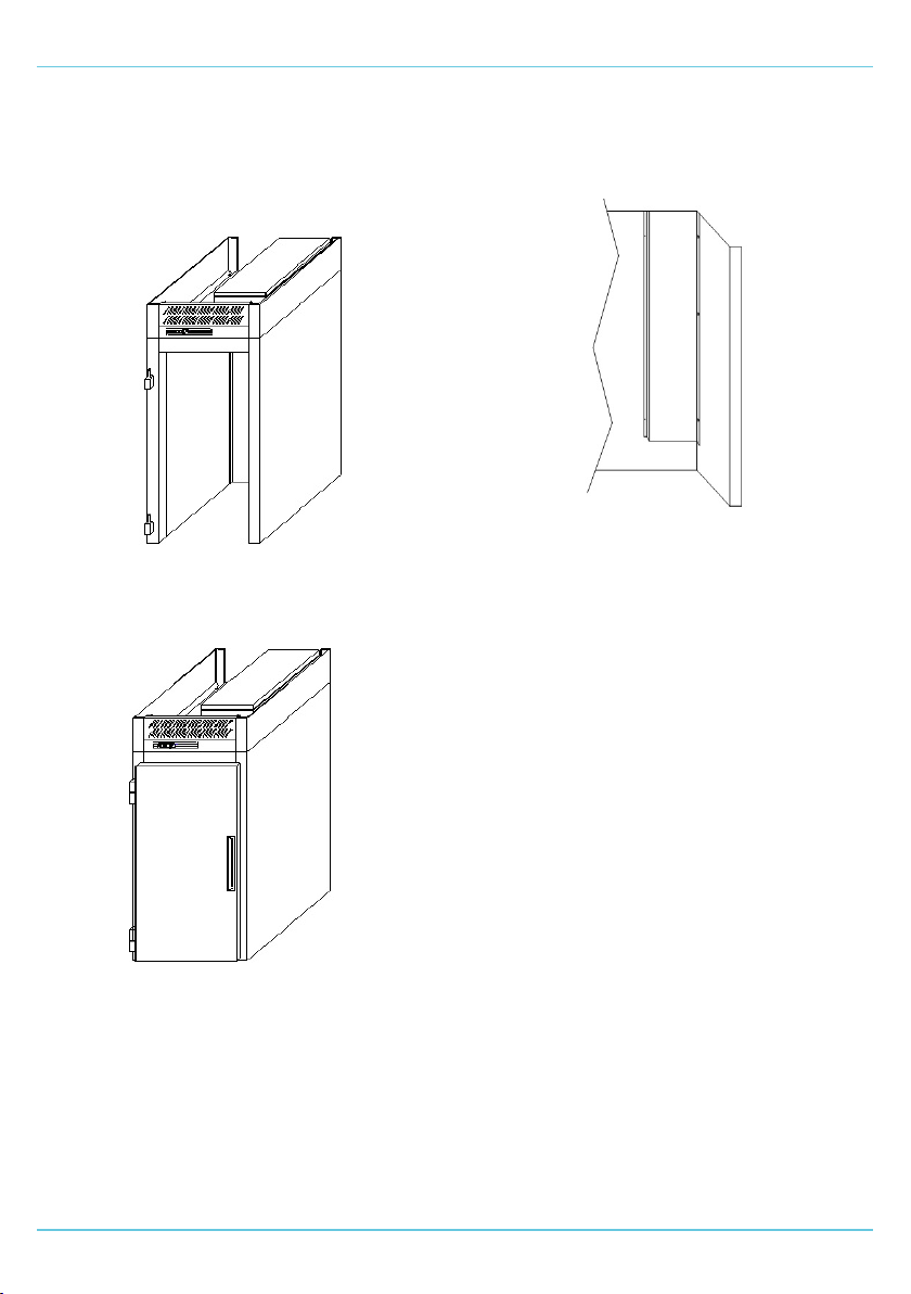
INSTALLATION FOR A RMR1T - ROLL IN MODULAR RUBY
INSTALLATION
Site Preparation
Please ensure that the oor area is clean and level.
Lay the insulated oor or oor tray if supplied.
Models with a 15mm oor
Put beads of food safe silicone sealant around the
oor as shown before assembling the wall panels.
Starting at a rear corner build the wall panels
together as per the Panel Assembly Instructions.
See gures 1-4.
FIG 4.
FIG 1.
FIG 2.
FIG 3.
INSTALLATION - RMR1T - ROLL IN MODULAR RUBY
6
Ensure all the walls and jambs have been located
and camlocked together before lowering the roof
section onto them.
Please note that the roof is very heavy.
See gure 5.
Fit the oor angle if supplied and then t the door
onto the door jamb by lowering vertically onto the
hinges. See gure 6.
Connect the door heater if provided.
IMPORTANT: electrical connection of the
heater must only be carried out by a qualied,
skilled and competent electrician. For further
information, refer to the equipment wiring
diagram.
FOR THAW MODELS
Fit the duct to the rear wall, right hand side wall and
roof inner with the screws provided in the pre-
punched holes. See gure 7.
INSTALLATION - RMR1T - ROLL IN MODULAR RUBY
FIG 5.
FIG 6.
FIG 7.

7
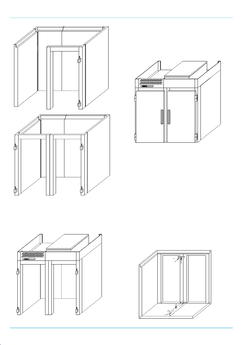
INSTALLATION FOR A RMR2T - ROLL IN MODULAR RUBY
INSTALLATION
Site Preparation
Please ensure that the oor area is clean and level.
Lay the insulated oor or oor tray if supplied.
Models with a 15mm oor
Put beads of food safe silicone sealant around the
oor as shown before assembling the wall panels.
Starting at a rear corner build the wall panels
together as per the Panel Assembly Instructions.
See gures 1-6.
INSTALLATION - RMR2T - ROLL IN MODULAR RUBY
FIG 1.
FIG 2.
FIG 3.
FIG 4.
8
INSTALLATION - RMR2T - ROLL IN MODULAR RUBY
Ensure all the walls and jambs have been located
and camlocked together before lowering the roof
section onto them.
Please note that the roof is very heavy.
See gure 7.
Fit the roof angle to the jambs and roof using the
screws provided. See ‘Fitting Roof Angle and Floor
Plate’.
Fit the oor angle if supplied and then t the doors
onto the door jamb by lowering vertically onto the
hinges. See gure 8.
Connect the door heaters if provided.
IMPORTANT: electrical connection of the
heater must only be carried out by a qualied,
skilled and competent electrician. For further
information, refer to the equipment wiring
diagram.
FITTING ROOF ANGLE AND FLOOR TIE
PLATE
Screw the roof angle to the roof and jambs as
indicated using the M5 screws supplied. See gure
9 (rooms with oors) or gure 10 (oorless rooms).
Screw the oor tie plate to the oor and jambs as
indicated using the 8 x 1/2 screws supplied. See
gure 9.
Please note that the oor tie plate is only
supplied with rooms with oors. Floorless
have either oor angle or oor tray.
FIG 5.
FIG 6.
FIG 7.
FIG 8.
FIG 9.

9
INSTALLATION - RMR2T - ROLL IN MODULAR RUBY
FOR THAW MODELS
Using the screws provided, t the air duct in the pre
punched holes to the centre of the back wall and
roof. See gure 11.
FITTING RAMPS
Fit the ramp to the front of the room with the screws
provided. See gure 12. Insert the screws into the
front face of the oor through the pre-punched
holes, do not screw in all completely, i.e. leave
them protruding by approximately 3mm. Hook the
ramp over the screws. The ramp is intended to be
removable for ease of cleaning.
FITTING FINISHING ANGLE (15MM FLOOR)
Fit nishing angle with screws provided. See gure
13.
FITTING THE AIR BAFFLE
Fit the air bae to the two fan pods. See gure 14
& 15.
FIG 10.
FIG 11.
FIG 12.
FIG 13.
Finishing angle
FIG 14.
Fan Guard
Fold tabs in by hand and
x to pod liner with 8 x
1/2” S/Steel screws
Screw
Screw
Screw
Bae
Fix ange to
fan guard with
8 x 1/2” S/Steel
screws

10
BULK HEAD LIGHT (OPTIONAL)
Secure the bulk head light to the back of the door
jamb legs with the screws provided. See gure 16.
IMPORTANT: electrical connection of the bulk
head light must only be carried out by a
qualied, skilled and competent electrician.
For further information, refer to the
equipment wiring diagram.
INSTALLATION - RMR2T - ROLL IN MODULAR RUBY
FIG 15.
FIG 16.
Fan Guard
Bae shown
xed in position
Ce manuel convient aux modèles suivants
2
Table des matières
Autres manuels Williams Réfrigérateur


