Wifibot U-TROOPER Manuel utilisateur

Quick Start Guide
Thank you for choosing the micro-trooper platform for your robotic
application.
• Before using the platform, please read with care this manual
• Keep this manual in a safe place for any future reference
• For updated information about this product visit the official
site of wifibot http://www.wifibot.com
Index
Package contents
Quick start
Platform overview
Platform interfaces
Battery installation
Computer and camera installation
RTMIX multi-robot interface
Connecting to the robot
Networking
Network configuration
Remote access
File transfer
Communication protocols
The USB key
1
…………………………………………………………………2
…………………………………………………………………2
…………………………………………………………………2
…………………………………………………………………3
…………………………………………………………………5
…………………………………………………………………7
…………………………………………………………………9
..………………………………………………………………13
......……………………………………………………………15
…….………………………………………………………….17
……….……………………………………………………….22
…………….………………………………………………….24
……………….……………………………………………….26
………………….…………………………………………….28
u-trooper
Package contents
Make sure to be in possession of all the
articles mentioned below. If any of them
should be missing, contact your reseller
as soon as possible.
Platform
IP camera
Two battery packs
Battery charger
USB key
Camera CD-ROM and documentation
1x charging cable
1x RJ45 cable for the IP camera
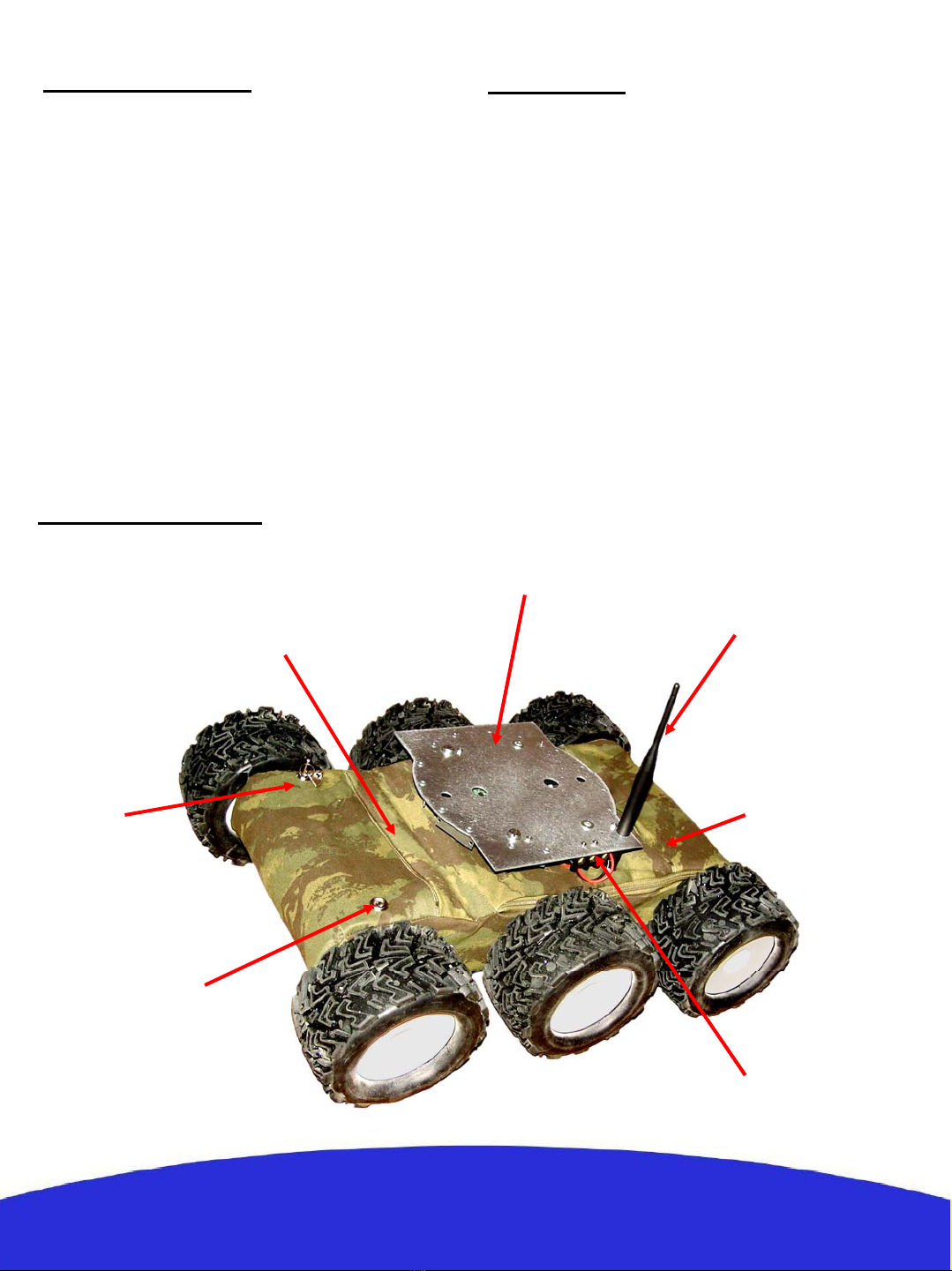
Platform overview
2
Front battery zip
Charging
connector
Power
ON/OFF
Rear battery zip
Antenna 5dBi
Power output
Aluminum support
Quick start
1- Install the RTMIX multi-robot interface and
reboot your computer (see page 9).
2- Switch ON the robot or robots.
3- Set you IP settings (see page 13) for example:
192.168.1.25 mask 255.255.255.0
4- Connect to the robots’ ad-hoc network
(see page 14)
5- Launch OLSR, select the appropriate network
device and press start.
6-LaunchRTMIX.
3
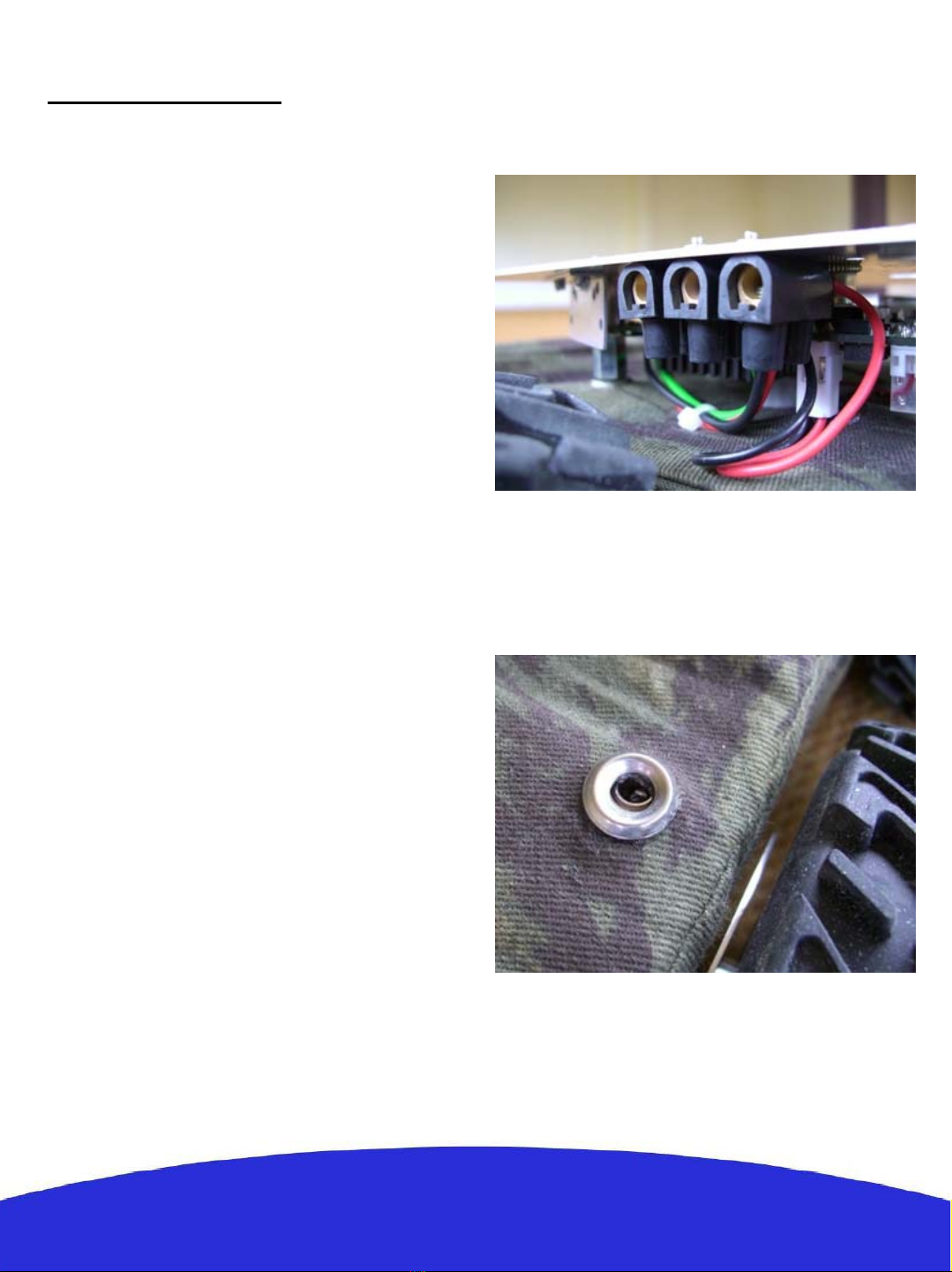
Platform interfaces
The 5V,GND and 12V power output:
A 5V output, GND and a 12V filtered battery
output are accessible on a screw clamp located
under the upper support. Red is 5V, black GND
and green the 12V output respectively. The 5V
output can’t give more than 6A and a maximum
of 6A is recommended too for the 12V output.
An incorrect use of this connector beyond those
values (short circuit or other) can provoke a
malfunction of the platform or of the DC/DC
converter and even damage it.
The charging connector:
This connector presents directly the + and –
of the platform batteries. This allows to plug
the included charger without the need of
taking the batteries out of their pockets for
charging them.
Note : When charging the platform make sure
the power switch is OFF so the charger does
not find the robot in march.

4
The ON/OFF switch:
The platform is switched ON and OFF by
turning a key. In order to avoid the possible loss,
the key should remain attached to the platform
at all times.
RS232 connector:
The low level motor control of the platform is
to be accessed through this connector using a
certain communication protocol (see the
RS232 protocol section).
The antenna connector:
This is the wi-fi antenna connector. Pass the
antenna through the upper support hole and
screw it carefully on the connector till the end.

Insertion:
1- Open the zip.
2- Find the connector and plug the battery pack.
3- Introduce the connector and battery cables
inside the pocket and push them at a side.
4- Introduce the battery diagonally into the
pocket with the cables on the down part. The
battery pack on the front has to be inserted
from right to left, while the battery pack on the
rear has to be inserted from left to right (see
photo).
5
Battery installation
The robot gets its power from two battery packs
with 5 Ni-MH cells each, with a capacity of
10000 mAH and a total nominal voltage of 12V.
Located on the front and rear parts of the
platform, their location into “pockets” has been
thought to facilitate their removal and
replacement. During normal operation the
battery packs remain inside the robot and need
only to be taken out in rare occasions.

6
5- Push the battery forward till the end.
6- Let the rear part of the battery pack come
down into the pocket.
Extraction:
Open the zip. Put your finger in the rear part of
the battery and push forward and pull up at the
same time to unlock the battery pack. Extract the
pack and unplug the connector.
Charge:
A battery charger is included with the platform.
First make sure the platform and the charger are
OFF, then connect the plugs of the charging
cable on the side of the charger and then on the
robot’s charging connector, finally switch the
charger ON and set the charging current.

Computer and camera installation
The platform is sold with an IP camera and an embedded computer which model can vary depending
of the version. Those are independent elements from the platform which can be replaced by any other
model. For more information about your particular camera and embedded computer please refer to
their respective manuals included in the USB key included with the robot. The top aluminum support
of the platform has been thought for the fixation of those and other user components.
Their installation takes place as follows:
Unscrew the upper
aluminum support:
Fix the embedded
computer on the down
part of the support :
7

8
Connect the power cable of the
computer and the camera on the
appropriate screw clamp:
Connect the RS232 and antenna
connector to the computer.
Screw back the aluminum support
on top of the platform and screw
the IP camera on top of the
support.

9
RTMIX multi-robot interface
Installation:
1- Unpack the zip file.
2- Double-click on Setup.
3- Unselect from the program list those you may already have
installed on your computer.
4- Click on the « install » button.
5- When asked to reboot your computer always say « no ».
6- Once installation is done, create a folder « rtmix » in the web
shared folder of the web server installed on your computer.
If you have followed the standard installation this would be
« C:/wamp/www/ »
10- Copy the containt of «C:/Program Files/RTMIX/monsite/»
into the «rtmix» folder you just created, ex:«C:/wamp/www/rtmix/»
11- Reboot your computer.

10
Features:
- The RTMIX multi-robot interface allows the user to control a team of up to four robots.
- The interface is best viewed with a 1024x768 resolution.
- Platform related controls are located on the left while visual related ones are located on the right.
- Before operation the user has to make sure all IP addresses and ports are correctly set.
- Selected robots can be controlled using the virtual joystick, a joystick or a wiimote, selecting more
than one robot at a time will have as a result having all of them receiving the same command.
- Cameras can be selected individually or blended in one image with RTMIX. Preset mixing layouts can
be selected and new ones added thanks to the “video source configuration” webpage.
- Certain functionalities need a reference which can be selected with a menu located just under the Mesh
and Map buttons.
- Certain types of supported cameras have incorporated relays which are set with the I/O checkbox.
- The “base” can be either an external gateway or the control computer itself (check “virtual” for this).
- The Map button needs to have an active internet connection and will show the robot’s and the base
position on a Google Maps webpage provided those are equipped with a GPS.
Signal to
Noise Ratio
(Linux only)
Speed of the
robot’s
mass center
Battery
level
Robot
Selection
Camera
selection
Reference for
SNR and MAP
Preset video
mixing selection
Robot IP
Input
channel
port
Output
channel
port
Not
implemented
Current video
selection
configuration
Camera type
selection
Controls for a
future charging
station
Camera IP
and port
Virtual
joystick
Video
window
Google
maps
Mesh
topology
graph
Camera relay
control
Configuration
port
Check
« virtual »
when localhost
is the base
Table des matières
Autres manuels Wifibot Robotique


Manuels Robotique populaires d'autres marques

STEMCenter USA
STEMCenter USA Pi-Bot v2.00 Manuel utilisateur

SunFounder
SunFounder PiDog Manuel utilisateur

Universal Robots
Universal Robots UR5 Manuel utilisateur

Universal Robots
Universal Robots E Series Manuel utilisateur

YASKAWA
YASKAWA MOTOMAN-MPL80 II Manuel utilisateur

EFORT
EFORT ECR5 Manuel d'instructions


