Wenglor P1KK008 Manuel utilisateur

Operating Instructions
EN
Translation of the Original Operating Instruction
Subject to change without notice
Available as PDF version only
Version: 1.5.0
Status: 07.12.2023
www.wenglor.com
P1KKxxx
Retro-Reex Sensors for Transparent Objects
High-End with Teach-in

2Table of Contents
Table of Contents
1. General��������������������������������������������������������������������������������������������������������������������������������������3
1.1 Information Concerning these Instructions .............................................................................................3
1.2 Explanations of Symbols ........................................................................................................................3
1.3 Limitation of Liability ...............................................................................................................................4
1.4 Copyrights...............................................................................................................................................4
2. For Your Safety ������������������������������������������������������������������������������������������������������������������������5
2.1 Use for Intended Purpose.......................................................................................................................5
2.2 Use for Other than the Intended Purpose...............................................................................................5
2.3 Personnel Qualifications .........................................................................................................................6
2.4 Modification of Products .........................................................................................................................6
2.5 General Safety Precautions....................................................................................................................6
2.6 Approvals and protection class...............................................................................................................6
3. Technical Data�������������������������������������������������������������������������������������������������������������������������� 7
3.1 Technical Data........................................................................................................................................7
3.1.1 Spot diameter...............................................................................................................................8
3.1.2 Smallest detectable part...............................................................................................................8
3.1.3 Switching distance .......................................................................................................................8
3.2 Complementary Products .......................................................................................................................9
3.3 Layout .....................................................................................................................................................9
3.4 Control Panel ........................................................................................................................................10
3.5 Scope of Delivery..................................................................................................................................10
4. Transport and Storage�����������������������������������������������������������������������������������������������������������10
4.1 Transport ..............................................................................................................................................10
4.2 Storage .................................................................................................................................................10
5. Installation and Electrical Connection���������������������������������������������������������������������������������11
5.1 Installation.............................................................................................................................................11
5.2 Electrical Connection ............................................................................................................................11
5.3 Diagnostics ...........................................................................................................................................12
6. Settings�����������������������������������������������������������������������������������������������������������������������������������14
7� I/O-Link������������������������������������������������������������������������������������������������������������������������������������14
7.1 Teach-In Mode......................................................................................................................................14
7.1.1 Minimal Teach-In (default setting)..............................................................................................14
7.1.2 Normal Teach-In ........................................................................................................................14
7.2 Dynamic readjustment ..........................................................................................................................14
7.3 Pin Function, E/AO2 .............................................................................................................................15
7.3.1 Input External Teach-In..............................................................................................................15
7.3.2 Error Output ...............................................................................................................................15
7.4 Additional functions and settings via IO-Link ........................................................................................16
8� I/O-Link������������������������������������������������������������������������������������������������������������������������������������16
9� Maintenance Instructions������������������������������������������������������������������������������������������������������16
10. Proper Disposal��������������������������������������������������������������������������������������������������������������������� 16
11� Appendix���������������������������������������������������������������������������������������������������������������������������������17
11.1 List of Abbreviations ...........................................................................................................................17
11.2 Change Index, Operating Instructions ................................................................................................17
11.3 Declarations of Conformity .................................................................................................................17

3Retro-Reflex Sensors for Transparent Objects
1� General
1�1 Information Concerning these Instructions
• These instructions apply to the product with ID code P1KKxxx.
• They make it possible to use the product safely and efficiently.
• These instructions are an integral part of the product and must be kept on hand for the entire duration of its
service life.
• Local accident prevention regulations and national work safety regulations must be complied with as well.
• The product is subject to further technical development, and thus the information contained in
these operating instructions may also be subject to change. The current version can be found at
www.wenglor.com in the product’s separate download area.
NOTE!
The operating instructions must be read carefully before using the product and must be kept
on hand for later reference.
1�2 Explanations of Symbols
• Safety precautions and warnings are emphasized by means of symbols and attention-getting words
• Safe use of the product is only possible if these safety precautions and warnings are adhered to
The safety precautions and warnings are laid out in accordance with the following principle:
Attention-Getting Word!
Type and Source of Danger!
Possible consequences in the event that the hazard is disregarded.
• Measures for averting the hazard.
The meanings of the attention-getting words, as well as the scope of the associated hazards, are listed below.
DANGER!
This word indicates a hazard with a high degree of risk which, if not avoided, results in death
or severe injury.
WARNING!
This word indicates a hazard with a medium degree of risk which, if not avoided, may result
in death or severe injury.
CAUTION!
This word indicates a hazard with a low degree of risk which, if not avoided, may result in
minor or moderate injury.
ATTENTION!
This word draws attention to a potentially hazardous situation which, if not avoided, may
result in property damage.
NOTE!
A note draws attention to useful tips and suggestions, as well as information regarding effi-
cient, error-free use.

4General
1�3 Limitation of Liability
• The product has been developed in consideration of the current state-of-the-art and applicable standards
and guidelines. Subject to change without notice.
• A valid declaration of conformity can be accessed at www.wenglor.com in the product’s separate download
area.
• wenglor sensoric elektronische Geräte GmbH (hereinafter referred to as “wenglor”) excludes all liability in
the event of:
• Non-compliance with the instructions
• Use of the product for purposes other than those intended
• Use by untrained personnel
• Use of unapproved replacement parts
• Unapproved modification of products
• These operating instructions do not include any guarantees from wenglor with regard to the described pro-
cedures or specific product characteristics.
• wenglor assumes no liability for printing errors or other inaccuracies contained in these operating
instructions, unless wenglor was verifiably aware of such errors at the point in time at which the operating
instructions were prepared.
1�4 Copyrights
• The contents of these instructions are protected by copyright law.
• All rights are reserved by wenglor.
• Commercial reproduction or any other commercial use of the provided content and information, in particular
graphics and images, is not permitted without previous written consent from wenglor.

5Retro-Reflex Sensors for Transparent Objects
2� For Your Safety
2�1 Use for Intended Purpose
The product is based on the following functional principle:
Retro-Reflex Sensors for Transparent Objects
Reflex sensors for transparent objects can be adjusted so precisely that they can reliably recognize highly
transparent objects such as glass, glass bottles or sheet products. Even shiny, chromed or reflective surfaces
can be reliably detected thanks to the integrated polarization filter.
The transmitter and receiver are located in a single housing and require a reflector to work. The output switch-
es if the light beam between the sensor and reflector is interrupted. The visible light spot of retro-reflex sensors
facilitates adjustment and commissioning. Depending on the sensor type, even small objects up to 0.1 mm can
be reliably detected over long distances.
This product can be used in the following industry sectors:
• Special machinery manufacturing
• Heavy machinery manufacturing
• Logistics
• Automotive industry
• Food industry
• Packaging industry
• Pharmaceuticals industry
• Plastics industry
• Woodworking industry
• Beverages industry
• Consumer goods industry
• Paper industry
• Electronics industry
• Glass industry
• Steel industry
• Aviation industry
• Chemicals industry
• Alternative energy
• Raw materials extraction
2�2 Use for Other than the Intended Purpose
• Not a safety component in accordance with 2006/42/EC (Machinery Directive).
• The product is not suitable for use in potentially explosive atmospheres.
• The product may only be used with accessories supplied or approved by wenglor, or combined with
approved products. A list of approved accessories and combination products can be accessed at
www.wenglor.com on the product detail page.
DANGER!
Risk of personal injury or property damage in case of use for other than the intended
purpose!
Use for other than the intended purpose may lead to hazardous situations.
• Observe instructions regarding use for intended purpose.

6For Your Safety
2�3 Personnel Qualifications
• Suitable technical training is a prerequisite.
• In-house electronics training is required.
• Trained personnel must have uninterrupted access to the operating instructions.
DANGER!
Risk of personal injury or property damage in case of incorrect initial start-up and
maintenance!
Personal injury and damage to equipment may occur.
• Adequate training and qualification of personnel.
2�4 Modification of Products
DANGER!
Risk of personal injury or property damage if the product is modified!
Personal injury and damage to equipment may occur. Non-observance may result in loss of
the CE and/or UKCA marking and the guarantee may be rendered null and void.
• Modification of the product is impermissible.
2�5 General Safety Precautions
NOTE!
• These instructions are an integral part of the product and must be kept on hand for the
entire duration of its service life.
• In the event of possible changes, the respectively current version of the operating
instructions can be accessed at www.wenglor.com in the product’s download area.
• Read the operating instructions carefully before using the product.
• Protect the sensor against contamination and mechanical influences.
2�6 Approvals and protection class

7Retro-Reflex Sensors for Transparent Objects
3� Technical Data
3�1 Technical Data
Order Number
Technical Data
P1KK
002 008 004 009
Optical Data
Range 2,000 mm
Reference reflector RQ100BA
Clear glass recognition yes
Switching hysteresis < 5 %
Light source Red light
Polarization filter yes
Service life (ambient temp. = +25° C) 100,000 h
Max. permissible ambient light 10,000 Lux
Aperture angle 3°
Single-lens optics yes
Spot diameter See table 1
Electrical Data
Supply power 10…30 V DC
IO-Link supply voltage 18…30 V DC
Current consumption (operating voltage = 24 V) < 20 mA
Switching frequency 1000 Hz
Switching frequency (speed mode) 2000 Hz
Response time 0,5 ms
Response time (speed mode) 0,25 ms
Temperature drift < 5 %
Temperature range −40…60 °C
Switching output voltage drop < 2 V
Switching output switching current 100 mA
Switching output residual current < 50 µA
Short-circuit protection yes
Reverse polarity protected yes
Overload-proof yes
Lockable yes
Interface IO-Link
IO-Link version 1.1
Protection class III
Output
function
PNP ×
NPN ×
NC, NO antivalent × ×
Mechanical Data
Setting method Teach-in
Housing material Plastic
Degree of protection IP67/IP68
Connection M8 × 1; 4-pin Cable,
4-wire, 2 m M8 × 1; 4-pin Cable,
4-wire, 2 m
Lens cover PMMA
Connection diagram 221 867 221 867

8Technical Data
3�1�1 Spot diameter
Range 0,5 m 1,3 m 2,0 m
Spot diameter 30 mm 100 mm 150 mm
Table 1
3�1�2 Smallest detectable part
Range 0,4 m 1 m 2 m
Smallest detectable part 2 mm 5 mm 8 mm
Table 2
3�1�3 Switching distance
Achievable switching distance depends on the utilized reflector. Nominal switching distance is achieved with
reflector types RQ100BA. Achievable ranges for other reflectors are listed in the following tables:
Reector Range
RQ100BA 0…2,00 m
RE18040BA 0…1,10 m
RQ84BA 0…1,60 m
RR84BA 0…1,90 m
RE9538BA 0…0,70 m
RE6151BM 0…1,50 m
RR50_A 0…1,05 m
RE6040BA 0…1,20 m
RE8222BA 0…0,85 m
RR34_M 0…1,00 m
RE3220BM 0…0,70 m
RE6210BM 0…0,45 m
RR25_M 0…0,55 m
RR25KP 0…0,30 m
RR21_M 0…0,50 m
ZRME01B01 0…0,25 m
ZRME03B01 0…0,90 m
ZRAE02B01 0…0,70 m
ZRMR02K01 0…0,35 m
ZRMS02_01 0…0,45 m
ZRAF08K01 0…0,40 m
ZRDF03K01 0…1,20 m
ZRDF10K01 0…1,30 m
RF505 0…0,40 m
RF508 0…0,40 m
RF258 0…0,40 m
Z90R004 0…0,70 m
Z90R005 0…1,00 m
Z90R006 0…1,00 m
NOTE!
In order to increase the stability in
the detection of highly transparent
objects, it is recommended to use
reflectors with micro structure.

9Retro-Reflex Sensors for Transparent Objects
3�2 Complementary Products
wenglor can provide you with suitable connection technology for your product.
Suitable mounting technology no.
Suitable connection technology no.
7
PNP-NPN converter BG7V1P-N-2M
IO-Link master
wTeach2 software DNNF005
3�3 Layout
P1KK002, P1KK004
P1KK008, P1KK009
1= Optical axis M3 screw = 0.5 Nm Dimensions specified in mm (1 mm = 0.03937”)
10 Transport and Storage
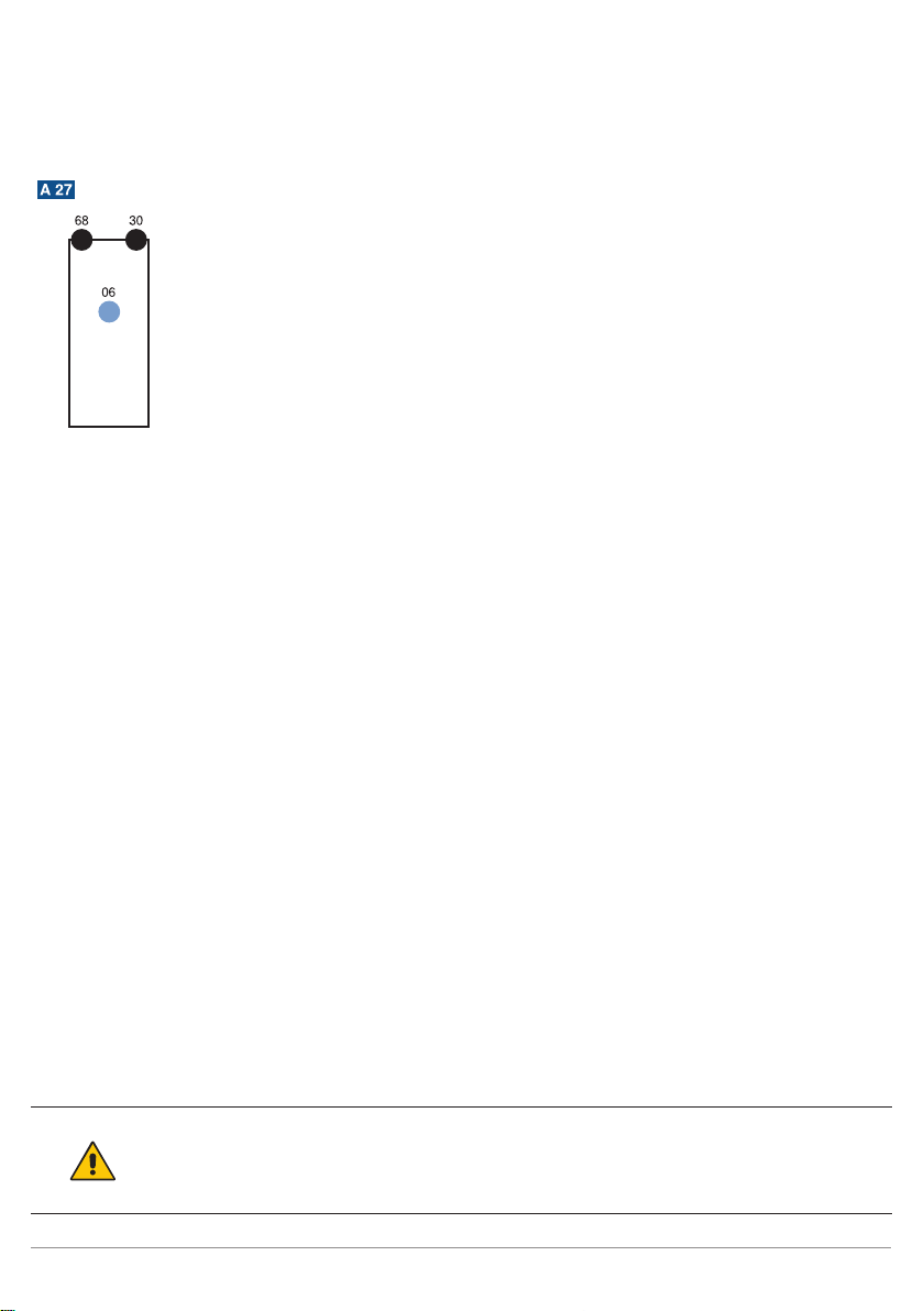
3�4 Control Panel
06 = teach-in key
30 = switching status indicator / contamination warning
68 = supply power indicator
3�5 Scope of Delivery
• Sensor
• Safety precautions
• Mounting-Set 01
4� Transport and Storage
4�1 Transport
Upon receipt of shipment, the goods must be inspected for damage in transit. In the case of damage, con-
ditionally accept the package and notify the manufacturer of the damage. Then return the device, making
reference to damage in transit.
4�2 Storage
The following points must be taken into condition with regard to storage:
• Do not store the product outdoors.
• Store the product in a dry, dust-free place.
• Protect the product against mechanical impacts.
• Protect the product against exposure to direct sunlight.
ATTENTION!
Risk of property damage in case of improper storage!
The product may be damaged.
• Storage instructions must be complied with.
Ce manuel convient aux modèles suivants
4
Table des matières
Autres manuels Wenglor Capteur de sécurité

Wenglor
Wenglor P2PY1 Series Manuel utilisateur

Wenglor
Wenglor Y1TA Series Manuel utilisateur

Wenglor
Wenglor IR 00 Series Manuel utilisateur

Wenglor
Wenglor I08G003 Manuel utilisateur

Wenglor
Wenglor IR2D001 Manuel utilisateur

Wenglor
Wenglor B60 Series Manuel utilisateur

Wenglor
Wenglor P1MH Series Manuel utilisateur

Wenglor
Wenglor SG4-I Manuel utilisateur

Wenglor
Wenglor P1PY1 Series Manuel utilisateur

Wenglor
Wenglor IR2D002 Manuel utilisateur


