Wen 6502 Manuel utilisateur

Model # 6502
BELT DISC SANDER
bit.ly/wenvideo
Your new tool has been engineered and manufactured to WEN’s highest standards for dependability,
ease of operation, and operator safety. When properly cared for, this product will supply you years
of rugged, trouble-free performance. Pay close attention to the rules for safe operation, warnings,
and cautions. If you use your tool properly and for intended purpose, you will enjoy years of safe,
reliable service.
IMPORTANT:
NEED HELP? CONTACT US!
Have product questions? Need technical support?
Please feel free to contact us at:
800-232-1195
WENPRODUCTS.COM
(M-F 8AM-5PM CST)

TABLE OF CONTENTS
Technical Data 2
3
4
6
7
8
12
14
15
17
19
General Safety Rules
Specific Safety Rules For Belt/Disc Sander
Electrical Information
Know Your Belt/Disc Sander
Assembly and Adjustments
Operation
Maintenance
Exploded View and Parts List
Warranty
TECHNICAL DATA
Model Number:
Motor:
Speed:
Disc Diameter:
Belt Size:
Belt Speed:
Belt Bed Tilt:
Belt Grit:
Dust Port Size:
Net Weight:
6502
120 V, 60 Hz, 4.3 A, 1/2 HP
3600 RPM (no load)
6˝
4˝ x 36˝
1900 SFM
0 to 90°
A80
2-1/4˝
41 lb
2
Troubleshooting

3
GENERAL SAFETY RULES
Safety is a combination of common sense, staying alert and knowing how your item works. SAVE THESE
SAFETY INSTRUCTIONS.
WARNING: To avoid mistakes and serious injury, do not plug in your tool until the following
steps have been read and understood.
1. READ and become familiar with this entire instruction manual. LEARN the tool’s applications, limitations,
and possible hazards.
2. AVOID DANGEROUS CONDITIONS. Do not use power tools in wet or damp areas or expose them to
rain. Keep work areas well lit.
3. DO NOT use power tools in the presence of flammable liquids or gases.
4. ALWAYS keep your work area clean, uncluttered, and well lit. DO NOT work on floor surfaces that are
slippery with sawdust or wax.
5. KEEP BYSTANDERS AT A SAFE DISTANCE from the work area, especially when the tool is operating.
NEVER allow children or pets near the tool.
6. DO NOT FORCE THE TOOL to do a job for which it was not designed.
7. DRESS FOR SAFETY. Do not wear loose clothing, gloves, neckties, or jewelry (rings, watches, etc.) when
operating the tool. Inappropriate clothing and items can get caught in moving parts and draw you in. ALWAYS
wear non-slip footwear and tie back long hair.
8. WEAR A FACE MASK OR DUST MASK to fight the dust produced by sawing operations.
WARNING: Dust generated from certain materials can be hazardous to your health. Always
operate the tool in a well-ventilated area and provide for proper dust removal. Use dust collection
systems whenever possible.
9. ALWAYS remove the power cord plug from the electrical outlet when making adjustments, changing parts,
cleaning, or working on the tool.
10. KEEP GUARDS IN PLACE AND IN WORKING ORDER.
11. AVOID ACCIDENTAL START-UPS. Make sure the power switch is in the OFF position before plugging
in the power cord.
12. REMOVE ADJUSTMENT TOOLS. Always make sure all adjustment tools are removed from the saw
before turning it on.
13. NEVER LEAVE A RUNNING TOOL UNATTENDED. Turn the power switch to OFF. Do not leave
the tool until it has come to a complete stop.

4
14. NEVER STAND ON A TOOL. Serious injury could result if the tool tips or is accidentally hit. DO NOT store
anything above or near the tool.
15. DO NOT OVERREACH. Keep proper footing and balance at all times. Wear oil-resistant rubber-soled foot-
wear. Keep the floor clear of oil, scrap, and other debris.
16. MAINTAIN TOOLS PROPERLY. ALWAYS keep tools clean and in good working order. Follow instruc-
tions for lubricating and changing accessories.
17. CHECK FOR DAMAGED PARTS. Check for alignment of moving parts, jamming, breakage, improper
mounting, or any other conditions that may affect the tool’s operation. Any part that is damaged should be properly
repaired or replaced before use.
18. MAKE THE WORKSHOP CHILDPROOF. Use padlocks and master switches and ALWAYS remove start-
er keys.
19. DO NOT operate the tool if you are under the influence of drugs, alcohol, or medication that may affect your
ability to properly use the tool.
20. USE SAFETY GOGGLES AT ALL TIMES that comply with ANSI Z87.1. Normal safety glasses only have
impact resistant lenses and are not designed for safety. Wear a face or dust mask when working in a dusty environ-
ment. Use ear protection such as plugs or muffs during extended periods of operation.
GENERAL SAFETY RULES
WARNING: Do not operate this tool until it is completely assembled and installed according to
the instructions.
1. This sander is designed to sand wood or wood-like products only. Sanding or grinding other materials could
result in fire, injury, or damage to the workpiece.
2. Use the sander on horizontal surfaces only. Operating the sander when mounted on non-horizontal surfaces may
result in motor damage or injury.
3. Fasten the sander securely to a bench top or supporting surface in order to stop it from tipping over or moving
when in use.
4. Make sure the sanding belt is installed in the correct direction. See directional arrow on back of belt.
5. Always have the tracking adjusted properly so the belt does not run off the pulleys.
6. Do not use sanding belts or discs that are damaged, torn, or loose. Use only correct size sanding belt and disc.
7. Always hold the workpiece firmly when sanding. Keep hands away from sanding belt or disc. Sand only one
workpiece at a time.
SPECIFIC RULES FOR THE BELT SANDER

5
SPECIFIC RULES FOR THE BELT/DISC SANDER
8. Always hold the workpiece firmly on the table when using the disc sander and when using the belt sander.
9. Always sand on the downward side of the sanding disc when using the disc sander. Sanding on the upward side
of the disc can cause the workpiece to fly out of position, resulting in injury.
10. Always maintain a minimum clearance of 1/16 inch (1.6 mm) or less between the table or backstop and the
sanding belt or disc.
11. Do not sand pieces of material that are too small to be safely supported.
12. When sanding a large workpiece, provide additional table height support.
13. Do not sand with the workpiece unsupported. Support the workpiece with the backstop or table. The only ex-
ception is curved work performed on the outer sanding drum.
14. Always remove scrap pieces and other objects from the table, backstop, or belt before turning the sander ON.
15. Never perform layout, assembly or set-up work on the table while the sander is operating.
16. Never use solvents to clean plastic parts. Solvents could dissolve or otherwise damage the material. Use only a
soft damp cloth to clean plastic parts.
17. Should any component of your sander be missing/damaged or fail in any way, shut off switch and remove plug
from power supply outlet. Replace the missing, damaged, or failed parts before resuming operation.
18. Never pull the power cord out of the receptacle. Keep cords away from heat, oil, and sharp edges.
19. Have an electrician replace or repair damaged or worn cords immediately.
ELECTRICAL INFORMATION
GROUNDING INSTRUCTIONS
IN THE EVENT OF A MALFUNCTION OR BREAKDOWN, grounding provides the path of least resistance
for an electric current and reduces the risk of electric shock. This tool is equipped with an electric cord that has an
equipment grounding conductor and a grounding plug. The plug MUST be plugged into a matching outlet that is
properly installed and grounded in accordance with ALL local codes and ordinances.
DO NOT MODIFY THE PLUG PROVIDED. If it will not fit the outlet, have the proper outlet installed by a
licensed electrician.
IMPROPER CONNECTION of the equipment grounding conductor can result in electric shock. The conduc-
tor with the green insulation (with or without yellow stripes) is the equipment grounding conductor. If repair or
replacement of the electric cord or plug is necessary, DO NOT connect the equipment grounding conductor to a
live terminal.

6
AMPERAGE REQUIRED GAUGE FOR EXTENSION CORDS
25 ft. 50 ft. 100 ft. 150 ft.
4.3 A 18 gauge 16 gauge 16 gauge 14 gauge
CHECK with a licensed electrician or service personnel if you do not completely understand the grounding
instructions or whether the tool is properly grounded.
USE ONLY THREE-WIRE EXTENSION CORDS that h a v e
three-pronged plugs and outlets that accept the tool’s plug as
shown in Fig. A. Repair or replace a damaged or worn cord im-
mediately.
CAUTION: In all cases, make certain the outlet in question is
properly grounded. If you are not sure, have a licensed electri-
cian check the outlet.
WARNING: This tool is for indoor use only. Do not expose to rain or use in damp locations.
Guidelines for using extension cords
Make sure your extension cord is in good condition. When using an extension cord, be sure to use one
heavy enough to carry the current your product will draw. An undersized cord will cause a drop in line
voltage resulting in loss of power and overheating. The table below shows the correct size to be used ac-
cording to cord length and nameplate ampere rating. When in doubt, use a heavier cord. The smaller the
gauge number, the heavier the cord.
Make sure your extension cord is properly wired and in good condition. Always replace a damaged exten-
sion cord or have it repaired by a qualified person before using it.
Protect your extension cords from sharp objects, excessive heat and damp/wet areas.
Use a separate electrical circuit for your tools. This circuit must not be less than a #12 wire and should be
protected with a 15 A time-delayed fuse. Before connecting the motor to the power line, make sure the
switch is in the OFF position and the electric current is rated the same as the current stamped on the motor
nameplate. Running at a lower voltage will damage the motor.
WARNING: This tool must be grounded while in use to protect the operator from electric shock.
ELECTRICAL INFORMATION
FIGURE A

7
AMPERAGE REQUIRED GAUGE FOR EXTENSION CORDS
25 ft. 50 ft. 100 ft. 150 ft.
4.3 A 18 gauge 16 gauge 16 gauge 14 gauge
KNOW YOUR BELT/DISC SANDER
ASSEMBLY AND ADJUSTMENTS
UNPACKING
WARNING: To avoid injury from accidental startups, turn switch OFF and remove the plug
from the power source outlet before making any adjustments.
Carefully unpack the belt/disc sander and all its parts, and compare against the list below. Do not discard
the carton or any packaging until the belt/disc sander is completely assembled.
INCLUDES (Fig. 1)
1. Socket Head Screws (2)
2. Miter Gauge (1)
3. Washers (2)
4. Work Support (1)
5. Hex Key 15/64” (1)
6. Worktable (1)
7. Adjustment Knob (1)
WORK SUPPORT
BELT TENSION
LEVER
BELT SANDING
AREA TRACKING
CONTROL
KNOB
MITER
GAUGE
DISC SANDING
AREA
ON/OFF
SWITCH
BASE BOLD-DOWN
AREA
DUST PORT
TABLE ANGLE
ADJUSTMENT
KNOB
DRIVE
DRUM
SANDING
BELT
SANDING
DISC

88
ASSEMBLY AND ADJUSTMENTS
ASSEMBLY
INSTALLATION OF SANDING DISC AND
GUARD
1. Peel backing away from sanding disc.
2. Align perimeter of disc with plate, and press disc
firmly into position on plate, leaving no loose edges.
3. Position disc guard against lower 1/3 of disc, align-
ing holes as shown. And use a screwdriver to fasten
the provided screws and washers securely.
MOUNT THE DISC SANDER TABLE
1. With the table in a horizontal position, line up and insert the pivot indexing pin with the pivot hole on the
frame. Hold in place.
2. Insert the handle into the threaded hole and tighten.
3. Adjust the table so that the edge is a maximum of 1/16 inch from the disc. Holding the table in this position,
tighten the three bolts on the top of the table.
WARNING: To avoid trapping the workpiece or fingers between the table and the sanding disc, the
table edge should be adjusted to a maximum of 1/16 inch from the sanding disc.

WRENCH
9
MOUNTING THE WORK SUPPORT
1. Align the Work Support with the hole.
2. Install a Lock Washer and a Flat Washer on the Hex Screw.
3. Insert the Hex Screw into the Work Support hole. Tighten.
4. Adjust the Work Support height to avoid contact with the
sanding belt.
MOUNTING THE SANDER TO WORKBENCH
WARNING - If during operation there is any tendency for the
sander to tip over, slide or walk on the supporting surface, the sander should be properly mounted to a
workbench or stand.
1. Position the sander on the workbench where
you expect/intend to use it.
2. Mark the workbench through the mounting holes located
in the sander base. Drill holes in the workbench at the marks.
3. Using long bolts, washers, locking washers and nuts as
shown (not supplied), secure the sander to the workbench.
Note: All bolts should be inserted from the top. Washers and
hex nuts should be fastened from the underside of the work-
bench.
INSTALL THE SANDING BELT
1. Loosen the bed locking screw with the hex key. Raise the sanding bed about 45°; tighten the bed locking screw.
2. Pull the tension lever, releasing the tension.
3. Locate the directional arrow on the smooth side of the
sanding belt.
4. Place the sanding belt over the drums with the direc-
tional arrow pointing towards the dust chute.
5. Center the belt correctly on both drums.
6. Push the tension lever back to tighten the belt to the
bed.
7. Loosen the bed locking screw; lower the bed to a hori-
zontal position. Tighten the bed locking screw.
ASSEMBLY AND ADJUSTMENTS
10
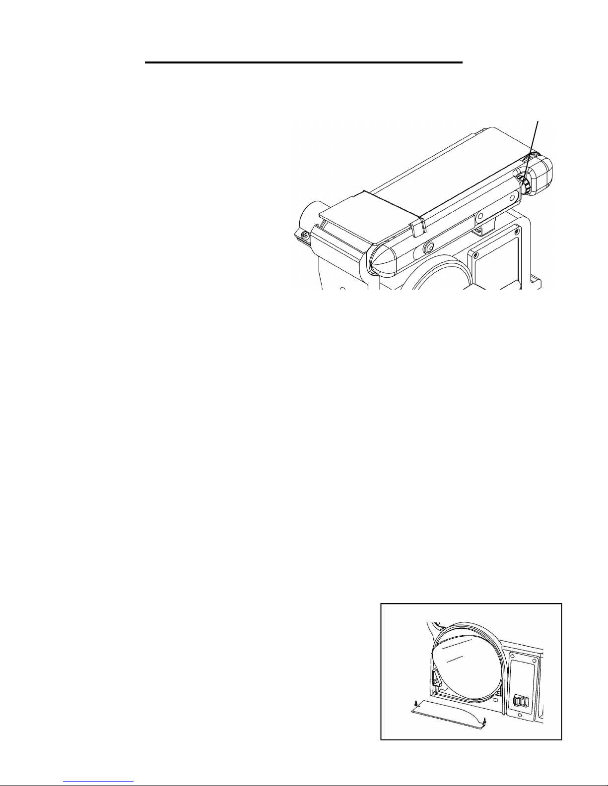
SANDING BELT TRACKING ADJUSTMENT
1. Plug in the power cord.
2. Turn the switch ON and OFF to make sure the
sanding belt is correctly centered and not sliding off
the idler and drive roller drums.
a. If the sanding belt moves toward the disc,
slightly turn the tracking knob counterclockwise.
b. If the sanding belt moves away from the disc,
slightly turn the tracking knob clockwise.
3. Turn the switch ON and OFF again; readjust the
tracking knob if necessary.
CHANGE SANDING BELT BED POSITION
The sanding bed can be used in the horizontal or vertical positions or any angle in between. To use in the vertical
position, do the following:
1. Loosen the bed locking screw with hex key, move the bed to the desired vertical position.
2. Tighten the locking screw when at desired position.
DUST PORT OPERATION
The dust port can be easily connected to a large diameter shop vacuum hose.
Sanding operations are inherently dusty. To help minimize the amount of dust that escapes into the surrounding
air, this sander is equipped with a 2-1/4” dust chute that can be easily connected to a dust-collection system. It is
strongly recommended that users employ a dust-collection system when using this belt & disc sander.
Use of a mask or respirator is still recommended even when a dust-collection system is in use.
INSTALL A NEW SANDING DISC
1. Remove the two screws from the sanding disc guard and remove the guard.
2. Remove the used sanding disc.
3. Wipe the sanding disc plate clean.
4. Peel the backing from the new sanding disc, align the disc with the
plate and press the sanding disc firmly on to the plate.
5. Reinstall the disc guard and tighten the screws.
ASSEMBLY AND ADJUSTMENTS
TRACKING KNOB
Autres manuels pour 6502
1
Table des matières
Autres manuels Wen Sander

Wen
Wen 6500T Manuel utilisateur

Wen
Wen 20401 Manuel utilisateur

Wen
Wen 94810 Manuel utilisateur

Wen
Wen The Detailer QIL-AJ2-150 Manuel utilisateur

Wen
Wen DW5084 Manuel utilisateur

Wen
Wen 6369 Manuel utilisateur

Wen
Wen AT1305 Manuel utilisateur

Wen
Wen 6301 Mode d’emploi

Wen
Wen 65910 Manuel utilisateur

Wen
Wen HB6319 Manuel utilisateur

Wen
Wen 6515 Manuel utilisateur

Wen
Wen 6510T Manuel utilisateur

Wen
Wen 6369 Manuel utilisateur

Wen
Wen 6010 Manuel utilisateur

Wen
Wen DW5062 Manuel utilisateur

Wen
Wen HB424V Manuel utilisateur

Wen
Wen AA6158 Manuel utilisateur

Wen
Wen 6362 Manuel utilisateur

Wen
Wen DW6395 Manuel utilisateur

Wen
Wen 6321 Manuel utilisateur


