WEDGELOCK I-LOCK Manuel utilisateur

THIS OPERATORS MANUAL MUST BE KEPT WITH THE CARRIER MACHINE AT ALL TIMES
Toll-free: 800 CASCADE (227.2233)
Telephone: 503-669-6257
NORTH AMERICA


3
NORTH AMERICA
PAGE
SECTION 1: SAFETY
1.0 I-LOCK™ SAFETY SYSTEM 3
1.1 INTEGRATED DESIGN FEATURES 4
1.2 SAFE COUPLER USE 5
SECTION 2: OPERATION
2.0 CONNECTING TO THE FIRST PIN 6
2.1 CONNECTING TO THE SECOND PIN 6
2.2 TO DISENGAGE THE SECOND PIN 7
2.3 TO DISENGAGE THE FIRST PIN 7
2.4 READY TO RE-CONNECT 8
2.5 NORMAL OPERATING PROCEDURE – FLOW DIAGRAM 9
SECTION 3: MAINTENANCE
3.0 COUPLER IDENTIFICATION 10
3.1 SERVICING SCHEDULE
SECTION 4: TROUBLE SHOOTING
4.0 TROUBLE SHOOTING GUIDE 11,12
SECTION 5: SAFE LIFTING PROCEDURE
5.0 SAFE LIFTING PROCEDURE 13
SECTION 6: WARRANTY
6.0 WARRANTY 14,15
SECTION 7: WARRANTY REGISTRATION
7.0 WARRANTY REGISTRATION FORM 16
CONTENTS

4
NORTH AMERICA
Congratulations on your purchase of the I-LOCKTM coupler. You have just bought the SAFEST
coupler in the world.
1.0 I-LOCK™ SAFETY SYSTEM
The I-LOCKTM Coupler by Wedgelock must be installed correctly utilizing our 3 hose circuit
technology. Correct installation ensures that the I-LOCK™ Coupler’s built in safety features operate
in accordance with the way in which the coupler has been designed.
INSTANT SAFETY
Most accidents occur in the rst 5 seconds of latching an attachment. Your coupler is tted with the
I-LOCKTM SAFETY SYSTEM which ensures that your attachment is locked the INSTANT that it is
latched (see gure 1.0.1). This means there is no danger of dropping the attachment if the primary
lock is not engaged completely. The I-LOCKTM SAFETY SYSTEM operates independently of the
primary lock.
MOST SERIOUS ACCIDENTS HAPPEN IN
THE FIRST 5 SECONDS OF LATCHING
THE WEDGELOCK ADVANTAGE
SAFETY
100%
50%
0%
1 2 3 4 5 6
ATTACHMENT CHANGE TIME IN SECONDS
ENGAGE FIRST
PIN with OTHER
COUPLER
ENGAGE PRIMARY
LOCK of OTHER
COUPLER
ENGAGE
SECONDARY LOCK
of OTHER COUPLER
NORMAL
OPERATION
ENGAGE FIRST
PIN with I-LOCK
NORMAL
OPERATION
ENGAGE PRIMARY
LOCK of I-LOCK
COUPLER
DANGER ZONE!
Key
I-Lock
Other
SECTION 1: SAFETY
(Fig 1.0.1)

5
NORTH AMERICA
OPERATOR CONTROLLED SAFETY KNUCKLE
The attachment can only be disconnected completely from the I-LOCK™ Coupler after the
intentional activation of the SAFETY KNUCKLE by the operator. The release switch has a built in
time delay. To retract the safety knuckle the operator manually activates the switch which allows
a 10 second timeframe to disengage the attachment. After 10 seconds the safety knuckle in the
I-LOCK™ mechanism will automatically reset. If the attachment has not been removed completely
the automatic reset of the safety knuckle will render the attachment into a safe situation again. If the
attachment has been removed the automatic reset of the safety knuckle ensures that the coupler is
ready to reconnect to the next attachment.
WEDGE LOCKING PRINCIPLE
Another safety feature of the I-LOCK™ Coupler is the Wedge Locking Principle. The locking
principle of the primary wedge provides at least 2.5 times the locking force compared with a swinging
jaw coupler. This assures that both attachment pins are locked rmly to the coupler body minimizing
the wear in the locking area of your coupler.
1.1 INTEGRATED DESIGN FEATURES:
Integral with the solenoid operated directional control valve are 2 pressure reducers set to: Locking
Pressure - 2100 PSI (145 BAR) and Unlocking Pressure - 3750 PSI (260 BAR). These ensure that
the hydraulic circuit is not over pressurized.
The solenoid valve is only energized to release the attachment. This will ensure that in the event of
an electrical failure the primary locking mechanism will stay in the locked position.
The electrical circuit is protected by a 10 Amp fuse.
Operation is by a dual rocker switch arrangement complete with warning buzzer. The warning
buzzer is present to alert the operator that the electric circuit is still live and the attachment can be
released.
The unique one piece hydraulic cylinder body eliminates port welding and potential feeder tube
damage. Integrated into the cylinder is a ‘Pilot Operated Safety Check Valve” which locks the
pressure in the extend side of the cylinder in the event of hose failure anywhere in the coupler
circuit. In addition, on the larger models, an internal pressure relief valve is tted to the cylinders to
protect against the potential of mechanically induced pressure spikes.
SECTION 1: SAFETY

6
NORTH AMERICA
Your I-LOCKTM Coupler will extend the overall length of the dipper arm.
ATTACHMENTS MAY HIT THE CABIN AND OR BOOM
Your I-LOCKTM Coupler may enable the operator to use buckets and
attachments for which it is not designed, i.e. oversized buckets or attachments.
ONLY USE ATTACHMENTS THAT ARE DESIGNED SPECIFICALLY FOR THE
HOST MACHINE.
Never place your hands inside the coupler or anywhere near the linkage
mechanism while the hydraulic system is pressurized or the carrier machine is
turned on.
Never use the Primary Locking Wedge or I-LOCK™ Safety Knuckle as a lifting
device.
FOR INFORMATION RELATING TO “SAFE LIFTING PROCEDURES” REFER
TO SECTION 5 OF THIS MANUAL.
Always fully engage the coupler to the bucket or attachment even if you just want
to lift or move the attachment to a different position on your work site.
Any damage deemed by Wedgelock to have been caused by operator misuse
will invalidate the manufacturers warranty set out in section 6.0 of this manual.
1.2 SAFE COUPLER USE
SECTION 2: OPERATION

7
NORTH AMERICA
2.0 CONNECTING TO THE FIRST PIN (Front Pin)
Switch Mode
The Lock-Out Switch is ON
The Momentary Switch is OFF
(Fig 2.0.1)
Buzzer Mode
The Audible Buzzer is sounding
(once every second)
I-Lock™ Coupler Mode
The Primary Wedge is retracted
The Safety Knuckle is in the safe position
(Fig 2.0.2)
Operator Action
Using the excavator arm control levers move front jaw of
the coupler over the rst pin (front pin) of the attachment.
Seat the rst pin into the front jaw. The I-LOCKTM Safety
Knuckle will instantly lock the coupler to the rst pin of the
attachment.
(Fig 2.0.3)
2.1 CONNECTING TO THE SECOND PIN (Rear Pin)
Operator Action
Using the excavator arm control levers simultaneously lift
and crowd the attachment until the second pin (rear pin)
is seated in the rear jaw section. Deactivate the Lock-Out
Switch – continue to activate the crowd lever, extending
the crowd cylinder - this will extend the Primary Wedge,
locking the second pin.
(Fig 2.1.1) RATTLE TEST TO CONFIRM CONNECTION
Switch Mode
The Lock-Out Switch is OFF
The Momentary Switch is OFF
(Fig 2.1.2)
Buzzer Mode
The Audible Buzzer is OFF
I-Lock™ Coupler Mode
The Primary Wedge is extended
The Safety Knuckle is in the safe position
(Fig 2.0.1)
(Fig 2.0.2)
(Fig 2.0.3)
(Fig 2.1.1)
(Fig 2.1.2)
SECTION 2: OPERATION
CONNECTION AN ATTACHMENT

8
NORTH AMERICA
2.2 TO DISENGAGE THE SECOND PIN (Rear Pin)
Operator Action
Using the excavator arm control levers position the
attachment slightly above the ground so the second
pin (rear pin) is lower than the rst pin (front pin).
Activate the Lock-Out Switch, this will retract the
Primary Wedge, unlocking the second pin.
(Fig 2.2.1)
Switch Mode
The Lock-Out Switch is ON
The Momentary Switch is OFF
(Fig 2.2.2)
Buzzer Mode
The Audible Buzzer is sounding
(once every second)
I-Lock™ Coupler Mode
The primary wedge is now retracted
The safety knuckle is in the safe position
The second pin is disengaged from the rear jaw
2.3 TO DISENGAGE THE FIRST PIN (Front Pin)
Operator Action
*Depress the Momentary Switch for more than one
second to activate the release of the Safety Knuckle.
Using the excavator arm control levers crowd the
I-Lock™ Coupler away from the rst attachment pin.
(Fig 2.3.1)
Switch Mode
The Lock-Out Switch is ON
The Momentary Switch is ON
(Fig 2.3.2)
Buzzer Mode
The Audible Buzzer is sounding
(twice every second)
I-Lock™ Coupler Mode
The Primary Wedge remains retracted
The Safety Knuckle is in the release position
(Fig 2.3.3)
After 5 to 10 seconds** the safety knuckle will reset to the
safe position and the Audible Buzzer will continue to sound
once every second (Fig 2.3.4)
(Fig 2.2.2)
(Fig 2.2.1)
(Fig 2.3.1)
(Fig 2.3.2)
(Fig 2.3.4)
DISCONNECTING AN ATTACHMENT
(Fig 2.3.3)
SECTION 2: OPERATION

9
NORTH AMERICA
PLEASE READ CAREFULLY
*Depressing of the Momentary Switch to activate the release of the
Safety Knuckle requires the operator to press down the rocker for
at least ONE second. After ONE second remove your nger from
the rocker to allow the Momentary Switch to reset. (the rocker will
automatically return to the rest position)
**The resetting of the Safety Knuckle is controlled by a timer, factory
set at 10 seconds. To adjust the timer refer to 2.5 Normal Operating
Procedure - (Flow Diagram)
2.4 READY TO RE-CONNECT
NOTE – Please read carefully
As soon as the Safety Knuckle automatically resets to the
safe position the Audible Buzzer will return to sounding
once every second. (Fig 2.4.1)
The I-Lock™ Coupler is ready to be re-connected to the
next attachment. (Fig 2.4.2)
To re-connect to your next attachment refer to:
SECTION 2.0 CONNECTING TO THE FIRST PIN
(Fig 2.4.1)
(Fig 2.4.2)
SECTION 2: OPERATION
10
NORTH AMERICA
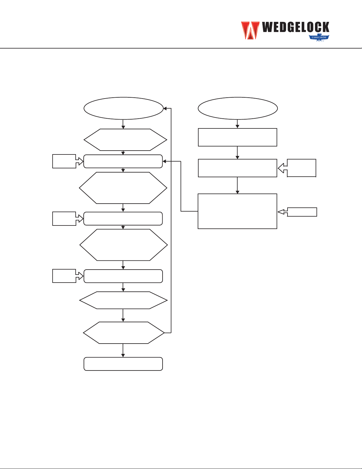
2.5 NORMAL OPERATING PROCEDURE - (FLOW DIAGRAM)
SECTION 2: OPERATION
Normal Operation
Power Off
Turn Power ON
using LOCK OUT
SWITCH
Wedge retracts
Safety unlocks
Press
MOMENTARY
SWITCH more
than 1 second
Remove
Attachment
5-10 second
window
Safety Resets Automatically
Connect
Attachment
Turn Power OFF
using LOCK OUT
SWITCH
Wedge extends
Timer Adjustment
Power Off
Press and hold
MOMENTARY SWITCH
Count beeps / second
Release MOMENTARY
SWITCH between 5 & 10
seconds to set timer
Turn Power ON using
LOCK OUT SWITCH
4 short beeps
4 short beeps
then 1 beep /
second
1 beep /
second
1 beep /
second
2 beeps /
second
Table des matières


