Watlow Controls 8LS Manuel utilisateur

8LS
User’s Guide
Part No. 10585-00. Revision 9.2
July 1996
Watlow Controls
1241 Bundy Blvd.
Winona, MN 55987
Customer Service
Phone: (800) 414-4299
Fax: (800) 445-8992
Technical Support
Phone: (507) 494-5656
Fax: (507) 452-4507
Email: wintechsupport@watlow.com

Copyright ©1996
Watlow Anafaze
Information in this manual is subject to change without notice. No part of this publication may be
reproduced, stored in a retrieval system, or transmitted in any form without written permission
from Watlow Anafaze.
Warranty
Watlow Anafaze, Incorporated warrants that the products furnished under this Agreement will be
free from defects in material and workmanship for a period of three years from the date of ship-
ment. The customer shall provide notice of any defect to Watlow Anafaze, Incorporated within one
week after the Customer's discovery of such defect. The sole obligation and liability of Watlow
Anafaze, Incorporated under this warranty shall be to repair or replace, at its option and without
cost to the Customer, the defective product or part.
Upon request by Watlow Anafaze, Incorporated, the product or part claimed to be defective shall
immediately be returned at the Customer's expense to Watlow Anafaze, Incorporated. Replaced or
repaired products or parts will be shipped to the Customer at the expense of Watlow Anafaze,
Incorporated.
There shall be no warranty or liability for any products or parts that have been subject to misuse,
accident, negligence, failure of electric power or modification by the Customer without the written
approval of Watlow Anafaze, Incorporated. Final determination of warranty eligibility shall be
made by Watlow Anafaze, Incorporated. If a warranty claim is considered invalid for any reason,
the Customer will be charged for services performed and expenses incurred by Watlow Anafaze,
Incorporated in handling and shipping the returned unit.
If replacement parts are supplied or repairs made during the original warranty period, the warranty
period for the replacement or repaired part shall terminate with the termination of the warranty
period of the original product or part.
The foregoing warranty constitutes the sole liability of Watlow Anafaze, Incorporated and the cus-
tomer's sole remedy with respect to the products. It is in lieu of all other warranties, liabilities, and
remedies. Except as thus provided, Watlow Anafaze, Inc. disclaims all warranties, express or
implied, including any warranty of merchantability or fitness for a particular purpose.
Please Note: External safety devices must be used with this equipment.

8LS User’s Guide i
Contents
Overview 1
System Diagram.....................................................................2
Parts List ..........................................................................2
Safety .....................................................................................3
Introduction 5
Specifications.........................................................................7
Analog Inputs...................................................................7
Control Capability............................................................8
Digital Outputs.................................................................8
Digital Inputs ...................................................................8
Pulse Counting Input .......................................................8
Serial Interface .................................................................8
Power Supply...................................................................8
Installation 9
Read This Before Installation ................................................10
Mounting The 8LS.................................................................11
External Wiring................................................................13
General Wiring Requirements .........................................13
Cable Recommendations .................................................15
Noise Suppression............................................................16
Terminal Block And Connector Layout ..........................18
RTB Connections.............................................................19
Analog Inputs...................................................................20
Input Scaling ..........................................................................21
Resistor Installation .........................................................22
Voltage Inputs..................................................................23
Milliamp Inputs................................................................23
Thermocouple Inputs .......................................................23
RTD Inputs ......................................................................24
Infrared Non-contact Temp. Sensors ...............................24
Pulse Input .......................................................................25
Carbon Probe Input..........................................................25
Control Outputs......................................................................27
PID Output Termination TB (Primary) or
Flat Ribbon (Secondary)..................................................27

ii 8LS User’s Guide
PID Control Relay Outputs..............................................28
Primary Screw Terminal Outputs ....................................28
Digital Outputs On The Screw Terminal Blocks.............29
Primary Analog Outputs ..................................................29
Analog Output Dip Switch Setting
for 0-5v/4-20mA ..............................................................30
CPU Dip Switch...............................................................31
Secondary Outputs 50 Pin Ribbon Cable ........................31
Communications Set-up and Connections.............................33
RS-232 Connections........................................................33
RS-485 Description And Connections.............................34
Using the 8LS 37
Front Panel.............................................................................37
Front Panel Keys..............................................................38
Displays .................................................................................40
Bar Graph Display ...........................................................40
Single Loop Display ........................................................41
Scanning Display .............................................................41
Alarm Display..................................................................41
Operator Menus .....................................................................43
Changing the Setpoint......................................................43
Selecting Status Mode .....................................................43
Autotune...........................................................................44
Ramp/Soak.......................................................................44
Setup 45
How to enter the Setup menus? .......................................45
How to edit a menu? ........................................................45
Setup Global Parameters Menu .............................................47
Save as Job.......................................................................48
Restore a Job....................................................................48
Set Alarm Delay...............................................................48
Set R/S Time Base ...........................................................49
Lock Panel .......................................................................49
Power Up Output Status ..................................................49
Controller Address...........................................................50
Communication Error Checking......................................50
Communication Baud Rate..............................................51
Communication Protocol .................................................51
AC Line Frequency..........................................................51
EPROM Version ..............................................................52
Setup Inputs Menu .................................................................53

8LS User’s Guide iii
Input Type........................................................................54
Pulse Sample Time ..........................................................55
Input Units .......................................................................55
Linear Scaling Menus ......................................................56
Input Offset ......................................................................58
Setup Control Menu...............................................................59
Heat/Cool PB ...................................................................60
Heat/Cool TI ....................................................................60
Heat/Cool TD...................................................................60
Heat/Cool Output Filter ...................................................60
Heat/Cool Spread .............................................................61
Setup Outputs Menu ..............................................................62
Output Type .....................................................................63
Cycle Time.......................................................................63
Output Action ..................................................................64
Output Limit ....................................................................64
Output Limit Time ...........................................................65
Nonlinear Output Curve...................................................65
Heat Output......................................................................66
Setup Alarms..........................................................................67
Alarm Types ....................................................................68
High Process Alarm Setpoint...........................................69
High Process Alarm Status ..............................................69
High Process Alarm Output Number...............................69
Deviation Band Alarm .....................................................70
Deviation Band Alarm Status ..........................................70
High Deviation Alarm Output Number ...........................70
Low Deviation Alarm Output Number............................71
Low Process Alarm Setpoint ...........................................71
Low Process Alarm Status...............................................71
Low Process Alarm Output Number ...............................72
Alarm Deadband ..............................................................72
Alarm Delay.....................................................................72
Test I/O ..................................................................................73
Digital Input Testing........................................................73
Test Output ......................................................................74
Digital Output Test ..........................................................74
Tuning and Control 75
Introduction............................................................................75
Control Modes .......................................................................76
Control Outputs................................................................78
Digital Output Control Forms..........................................78

iv 8LS User’s Guide
Setting Up and Tuning PID Loops ........................................80
General PID Constants by Application..................................82
Troubleshooting 85
Stand Alone Systems .............................................................85
Checking Control Outputs ...............................................85
Checking Digital I/O........................................................85
Computer Supervised Systems ..............................................86
Computer Problems .........................................................86
Computer Software ..........................................................86
Communications Problems ..............................................87
Serial Interface .................................................................87
Appendix A: Ramp Soak 89
Introduction............................................................................89
R/S Features.....................................................................89
Specifications...................................................................90
Configuring Ramp/Soak ........................................................90
Setting the R/S Time Base...............................................91
Editing R/S Parameters....................................................91
Choosing a Profile to Edit................................................91
Copying the Setup from Another Profile.........................92
Editing the Tolerance Alarm Time ..................................92
Editing the Ready Setpoint ..............................................93
Editing the Ready Event States........................................93
Choosing an External Reset Input ...................................94
Editing a Segment............................................................94
Setting Segment Time......................................................94
Setting a Segment Setpoint ..............................................95
Configuring Segment Events ...........................................95
Editing Event Outputs......................................................96
Changing Event States .....................................................96
Editing Segment Triggers ................................................96
Assigning an Input to a Trigger .......................................97
Changing a Trigger’s True State......................................97
Latching or Unlatching a Trigger ....................................97
Setting Segment Tolerance ..............................................98
Ending a Profile ...............................................................98
Repeating a Profile...........................................................98
Using Ramp/Soak ..................................................................99
Assigning a Profile to a Loop...........................................99
Running a Profile .............................................................100
Ramp/Soak Displays........................................................101

8LS User’s Guide v
Holding a Profile or Continuing from Hold.....................103
Resetting a Profile............................................................104
Appendix B: 8LS-CP 105
Key Features ....................................................................105
System Configuration ............................................................106
Specifications.........................................................................108
Analog Inputs...................................................................108
Control Capability............................................................108
CP Control .............................................................................109
Trim Gas Temperature Alarm Output ...................................109
Recommended CP Trim Gas Alarm for Continuous
Applications .....................................................................109
Recommended CP Trim Gas Alarm for Batch Applications110
Carbon Probe .........................................................................111
General Guidelines ..........................................................111
Probe Burn Off.......................................................................112
Carbon Probe Burn Off Requirements: ...........................112
Burn Off Procedures ........................................................112
Burn Off Function............................................................113
Setup Menus ..........................................................................114
Setup Inputs .....................................................................114
Setup Carbon Burn Off ....................................................116
Setup Alarms....................................................................119
CP and DP Display ..........................................................119
Appendix C: 8LS Cascade 121
Introduction............................................................................121
8LS Cascade Menus...............................................................121
Cascade Main Menu ........................................................121
Choosing the Primary Loop.............................................122
Setting the High End of the Secondary Setpoint .............122
Setting the Low End of the Secondary Setpoint ..............122
Glossary 123

vi 8LS User’s Guide

Overview
8LS User’s Guide 1
Overview
This manual describes how to install, setup, and operate an 8LS
controller. Included are six chapters, Appendixes describing the 8LS-CP
(Carbon Potential) and the 8LS-RS (Ramp/Soak), and a glossary of
terms. Each chapter covers a different aspect of your control system and
may apply to different users. The following describes the chapters and
their purpose.
• Introduction: Gives a general description of the 8LS and its related
specifications.
• Installation: Describes how to install the 8LS.
• Using the 8LS: Provides an overview of system displays and opera-
tor menus.
•
Setup: Describes all the setup displays for the controller, and how to
access them.
• Tuning and Control: Explains PID control and provides tips for
tuning your system.
• Troubleshooting: Gives some basic guidelines for solving control
problems.
•
Appendix A: Describes the Ramp and Soak function in the 8LS con-
troller.
• Appendix B: Describes the 8LS-CP controller—its function, fea-
tures, and additional menus.
2 8LS User’s Guide
Overview
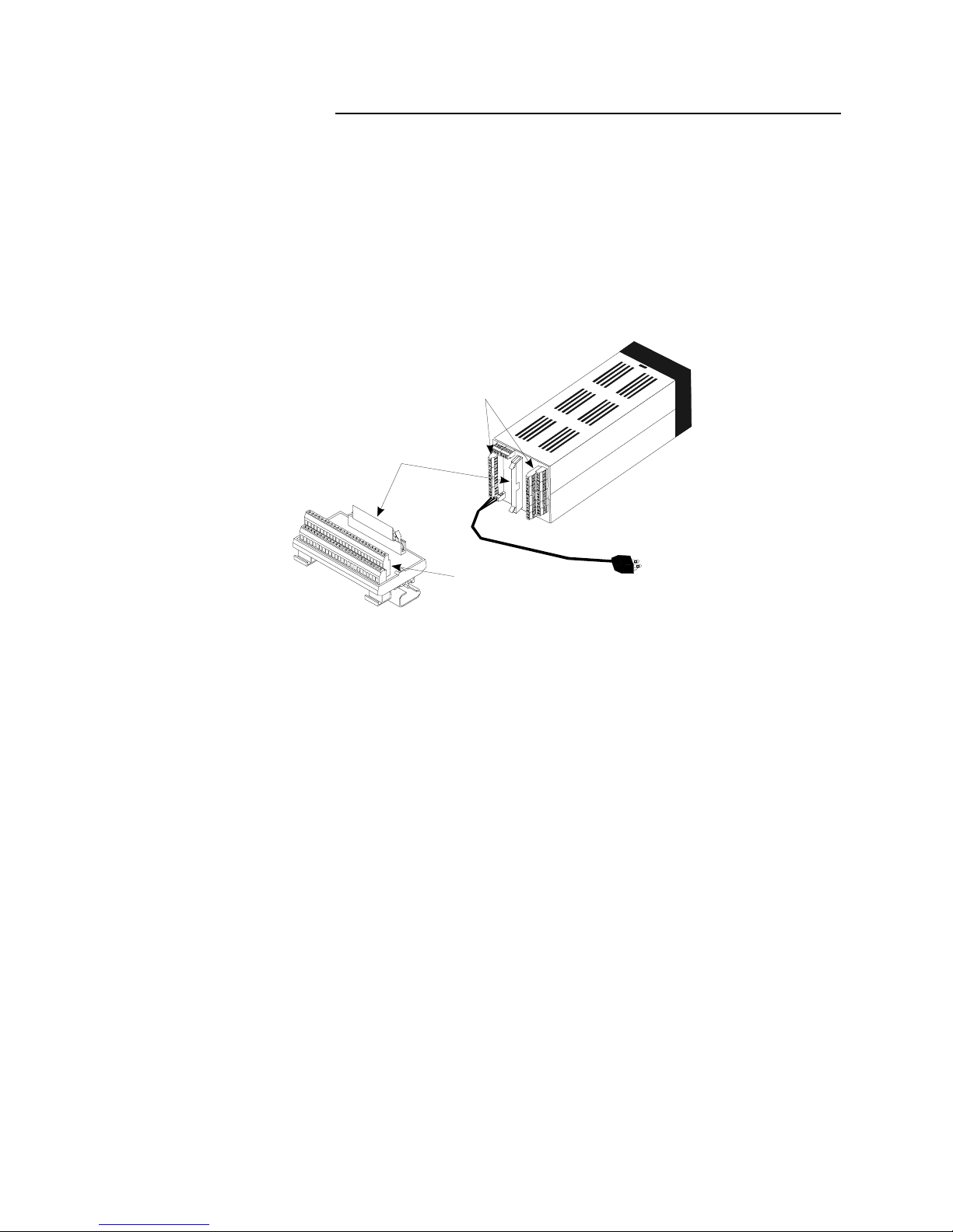
System Diagram
The illustration below shows how the parts of the 8LS are connected.
When unpacking your system, use the diagram and parts list below to
ensure all parts have been shipped. Please don’t hesitate to call Watlow
Anafaze’s Technical Service Department if you have problems with
your shipment, or if the 8LS components are missing or damaged.
Parts List
•8LS controller
•Controller mount kit
•RTB
•50 pin flat ribbon cable
•8LS manual
50-Pin Ribbon Cable
8LS to RTB
50-Pin RTB
8LS
Secondary Outputs
and Alarms
Signal Inputs and
Primary Outputs
System Power
Table des matières
Manuels Équipement d'enregistrement populaires d'autres marques


Strymon
Strymon NIGHTSKY Manuel utilisateur

Mitsubishi Electric
Mitsubishi Electric 16CH DIGITAL RECORDER DX-TL5000U Manuel utilisateur

Tews Technologies
Tews Technologies TPMC465 Manuel utilisateur

Honeywell
Honeywell Excel 50 Manuel utilisateur

SeaLevel
SeaLevel COMM+8.LPCI Manuel utilisateur

Arturia
Arturia AUDIOFUSE STUDIO Manuel utilisateur


