Wanco WSP12 Manuel utilisateur

Silent Power Series Generator
Operator Manual
Model WSP12 with DSE6020 Controller
PN: 221235

Page | 2
Thank you for purchasing a Wanco Silent Power Series three-phase diesel generator set. This manual
contains important safety and operating information - please read the complete manual before attempting
to operate the generator.
All information in this publication is based on the latest product information available at the time of approval
for printing. We reserve the right to make changes at any time without notice.
No part of this publication may be reproduced without written permission.
Throughout this manual pay special attention to statements preceded by the following signal words:
Failure to properly follow these precautions is likely to result in property damage,
serious injury or death
Failure to properly follow these precautions can result in property damage,
serious injury or death
Indicates a possibility of personal injury or equipment damage if instructions are
not followed
Gives helpful information.
If you need assistance with your generator set, please contact our service department using the following
information:
Wanco Inc.
5870 Tennyson Street
Arvada, Colorado 80003
303-427-5700
fax 303-427-5725
www.wanco.com
If you need technical assistance with the alternator, please contact Mecc Alte directly:
Visit: www/meccalte.com –Support –Service Network –North America to locate a qualified service center
or contact the US office directly at:
MECC ALTE INC.
1229 ADAMS DRIVE - 60051
MCHENRY - ILLINOIS
USA
If you need technical assistance with the Perkins engine, please contact your local Perkins Distributor or
call Wanco Inc.

Page | 3
CONTENTS
1. SAFETY INSTRUCTIONS .....................................................................4
2. QUICK START CHECKLIST ..................................................................6
3. MAJOR COMPONENT LOCATIONS.....................................................7
4. OPERATION ..........................................................................................11
5. MAINTENANCE.....................................................................................12
6. FLUIDS & COMMON SERVICE PARTS................................................13
7. TROUBLESHOOTING ...........................................................................13
8. SPECIFICATIONS .................................................................................14
9. WIRING DIAGRAM................................................................................15
10. TOWING ..............................................................................................16
Read and understand this Operator Manual before starting the generator. Failure to do so could
result in personal injury or equipment damage.
Refer to the Perkins Engine Operation & Maintenance Manual for important engine-specific
information.

Page | 4
SAFETY INSTRUCTIONS
Electric Shock Hazard.
Contact with electric power lines will cause serious injury or death.
Contact with AC output terminals or other live electrical circuits on
this generator during operation will result in severe injury or death.
Only qualified service personnel should attempt to service the
generator electrical systems.
Explosion Hazard.
Keep Engine, fuel and other combustibles away from sparks, open
flame and burning objects.
Do not smoke near the generator.
Stop the engine before filling or draining the fuel tank.
Use only diesel fuel –do not fuel with gasoline.
Replace the fuel tank cap after refueling.
Do not use gasoline or other highly flammable solvents for cleaning.

Page | 5
Electric Shock Hazard
Disconnect the cranking battery negative terminal and/or disengage
the battery at the Battery Disconnect Switch before servicing any part
of the engine, alternator or generator controls.
Moving Parts Hazard
Disconnect the cranking battery negative terminal and/or disengage
the battery at the Battery Disconnect Switch before servicing any part
of the engine, alternator or generator controls.
Risk of Sever Burns.
Do not touch the exhaust system or areas near the exhaust at rear of
trailer.
Do not remove radiator cap when engine is hot. Contents are hot and
under pressure.

Page | 6
GENSET QUICK START/STOP CHECKLIST
These instructions are for starting the generator set in Manual Mode.
Read the entire genset Operator Manual before starting the engine
Pre-Startup Checks
Check coolant level, oil level and confirm that you have sufficient fuel.
Confirm the Fuel Valve is in the correct position for the fuel source (skid tank or external supply).
Confirm the Estop button is in Run mode (turn it clockwise to release).
Place the Battery Switch in the ON position.
Control Panel
Confirm the Main Circuit Breaker is in the OFF position.
Turn the Deepsea controller ON and address any alerts or warnings.
Press the red Stop/Reset button and then the Manual Mode button.
Press the green Start button and wait a few seconds for the engine to start.
Allow the engine to warm up, then switch the Main Circuit Breaker ON.
Monitor the generator and loads as needed to assure proper operation.
Shutting Down the Genset
Do not use the Estop button to stop the generator except in an emergency
Confirm that your loads are ready to lose power.
Switch the Main Circuit Breaker OFF
Press the Stop/Reset button to stop the engine.
Turn the Deepsea controller OFF.
Place the Battery Switch in the OFF position to avoid battery drain between uses.

Page | 7
MAJOR COMPONENT LOCATIONS
Generator left-side view (from operator’s position)
Generator right-side view (from operator’s position)
Lift Hook
Coolant Drain
Forklift Access (2X)
Control Panel
Emergency Stop
Switch
Receptacles & Circuit
Breakers
Oil Drain
Containment
Vessel Cleanout &
Diesel Tank Drain
External Diesel
Connections
Page | 8
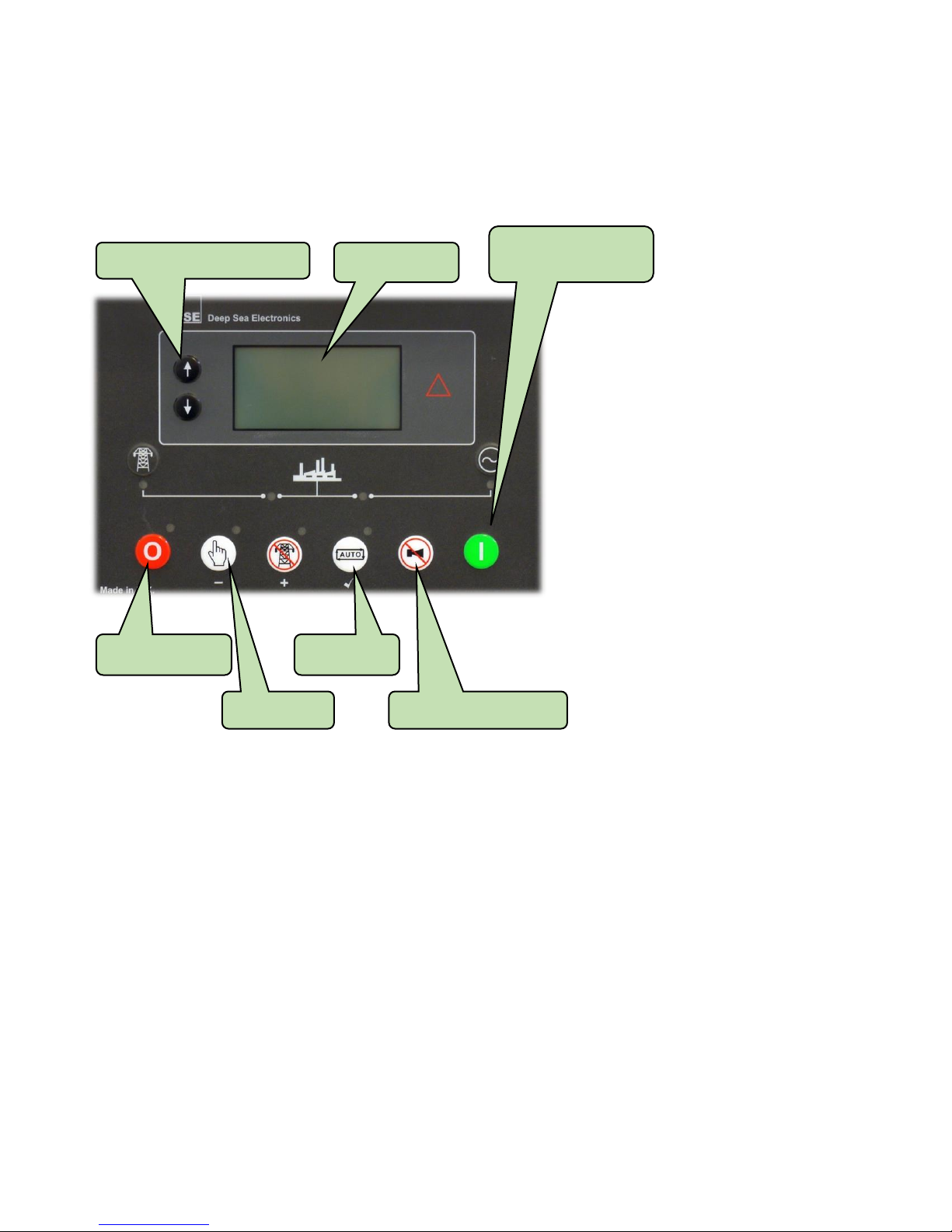
The Deepsea Genset Controller:
Located in the Control Panel at the operator end of the generator.
Refer to the DSE6020 Mk II Operators Manual for additional information
Menu Navigation:
Use the Up-Down Navigation Buttons to access various menus
Menu Navigation Buttons
Stop/Reset Mode
Manual Mode
Auto Mode
Mute Alarm & Lamp Test
Start Engine (Manual
Mode only)
Display

Page | 9
Lower AC Connection Panel
Located behind the flip-up panel on the generator right side.
Emergency Stop Switch
Located outside, beside the AC electrical connection panel on the generator right
side.
The Emergency Stop Switch shuts down the engine immediately –for Emergency
use only. See the Operating Section for instructions on normal engine shutdown.
Circuit Breakers for
Receptacles
120V GFCI Receptacles
120/240V CS6369
Receptacles
120V NEMA TT30 RV
Receptacle
120/240V NEMA L14-30
Receptacle
Main Circuit Breaker

Page | 10
Main Circuit Breaker
Located in the Connection Panel near the receptacles.
The Main Circuit Breaker is present to protect the AC alternator windings from
overload damage. When the circuit breaker is in the ON position, current can flow
from the alternator to the AC output connections. When in the OFF position, no
current or voltage will be present at any AC output connection.
This circuit breaker may switch OFF during operation if it detects an overload
condition.
Battery Disconnect Switch
Located inside the engine compartment on the generator right side.
Disconnects the cranking battery from all 12VDC systems, including the
controller and relays. This switch must be ON for the Controller to operate and
for starting the engine. Shown in the OFF position here.
Table des matières
Autres manuels Wanco Générateur portable


