Vision V1/400/A Instructions de montage

INSTALLATION & USER INSTRUCTIONS
SUITABLE FOR USE ON NATURAL GAS (G20) AT 20mbar SUPPLY PRESSURE
These instructions must be left with the appliance for future reference and
V1/100 Rev.1 (Dec 2011) VISION FIRES
GB IE
Model Number: V1/400/A (manual control)
DECORATIVE OPEN FRONT
COAL EFFECT GAS FIRE

CONTENTS
TECHNICAL INFO 3
Appliance Information 3
Efficiency Information 3
Ventilation Requirements 3
INSTALLATION REQUIREMENTS 4
General Installation Conditions 4
Flue/Chimney Suitability and Inspection 4
Preparation of the Fireplace Opening 5
Shelf Position 5
Fireguard Requirements 5
APPLIANCE INSTALLATION 6
Unpacking the Fire 6
Fitting the Appliance 6
Fuel Bed Assembly 7
Fire Front 10
Lighting the Appliance 10
Spillage Test 11
Review & Handover 11
SERVICING AND MAINTENANCE 12
Servicing 12
Removing the Burner Assembly 12
SPARES 12
USER GUIDE 13
General Information 13
Operating Procedure 14
Spillage Safety System 15
Cleaning 15
Ceramic Fuel Bed 15
Fascia 15
TECHNICAL INFORMATION
2

TECHNICAL INFORMATION
APPLIANCE INFORMATION
This appliance should be used with Natural Gas (G20) only.
Model: V1/400/A
Gas Type G20 natural gas
Maximum Gross Input 6.85kW (23,400 Btu/h)
Minimum Gross Input 3.8kW (13,000 Btu/h)
Inlet Pressure 20mbar ±1.5mbar
Gas Connection 8mm pipe
Ignition Piezo Electric
Burner Injector Cat 82—074
Pilot Type Seagas P432D
NOx Classification 5
EFFICIENCY
There are no efficiency requirements appropriate for this type of appliance as it is intended for
decorative use. For SAP purposes the efficiency should be calculated as 20% for use in the
Space Heating Requirements calculation.
VENTILATION REQUIREMENTS
In the UK, purpose made ventilation is not normally required for this appliance except in new
build houses. However, if spillage is detected during commissioning of the appliance, this may
mean there is insufficient ventilation. Additional ventilation may then be required. Please refer to
any national ventilation requirements in this instance. In the ROI, it will be necessary to refer to
I.S. 816 issued by the National Standards Authority of Ireland.
Any air vent must not be restricted.
TECHNICAL INFORMATION
3

INSTALLATION REQUIREMENTS
GENERAL INSTALLATION CONDITIONS
In the United Kingdom it is law that all gas appliances are fitted by a competent person in
accordance with the most up to date edition of the Gas Safety (Installation and Use) Regulations.
Failure to install the appliance correctly could lead to prosecution.
The installation must also be in accordance with all relevant parts of the Local and National
Building Regulations, all relevant code of practice, and all applicable requirements of the
following British Standards:
BS EN 1856 Part 1 Chimneys - Requirements for metal chimneys.
BS EN 1858 Chimneys - Components - Concrete flue blocks.
BS EN 1806 Chimneys - Clay/ceramic flue blocks.
BS EN 1856 Part 1 Chimneys - Requirements for metal chimneys.
BS 5440 Parts 1 & 2 Installation of Flues and Ventilation.
BS 6461 Part 1 Masonry chimneys & flues - Installation.
BS 5871 Part 2 Installation - Inset LFE gas fires.
BS 6891 Gas pipework installation.
BS 1251 Open fireplace components.
FLUE/CHIMNEY SUITABILITY AND INSPECTION
This appliance is for use with 225mm x 225mm conventional brick built chimneys and fabricated
flues.
If the chimney has previously been used for solid fuel, the chimney must be swept before
installation of the appliance.
Minimum size of all flues: 175mm diameter or equivalent area.
Minimum effective height of all flue types: 3 metres.
Single wall, twin wall or flexible flue liner must be stainless steel or aluminium and conform to BS
EN 1856 Part 1.
The flue system must conform to BS 5440 Part 1 in design and installation.
The flue must not be used for any other appliance. Any dampers or register plates must be
removed or locked in the open position.
4

INSTALLATION REQUIREMENTS
PREPARATION OF THE FIREPLACE OPENING
The appliance must be installed mounted on a non-combustible hearth. It must not be installed
directly on any combustible material. The hearth must be at least 12mm thick with a periphery
thickness of at least 50mm. It should be at least 700mm wide and project at least 300mm for-
wards from the fire opening.
The appliance must be fitted into a non combustible opening.
The appliance requires a nominal 16” (400mm) fire back and when installed, the height of the
fire opening from the hearth should not exceed 22” (560mm).
The floor within the fireplace opening should be reasonably flat to ensure a good seal can be
made at the bottom of the appliance.
Any underfloor air supply to the fire opening must be sealed off completely.
The appliance can be fitted with a non combustible fireplace surround or a proprietary fireplace
surround with a temperature rating of at least 150°C.
SHELF POSITION
The appliance can be installed below a combustible shelf as long as there is a minimum distance
of 750mm from the top of the hearth and the shelf does not project more than 150mm. If the shelf
projects more than 150mm then the distance between the top of the hearth and the shelf needs to
increase by 15mm for every additional 25mm of projection beyond 150mm.
FIREGUARD REQUIREMENTS
A fireguard complying with BS 8423 should be fitted for the protection of children, the elderly,
the infirm and pets.
TECHNICAL INFORMATION
5

APPLIANCE INSTALLATION
UNPACKING THE FIRE
Carefully remove the appliance from the carton, taking special care with any ceramic
components. Remove all loose item packaging and check for all components which should
include:
1 x Gas fire burner assembly
1 x Box containing ceramic components.
1 x Installation and User Instruction manual
1 x Loose parts pack including:
1 x Inlet ‘T’ connector
1 x Nut & olive for 8mm inlet pipe.
2 x Fixing screws and plugs.
FITTING THE APPLIANCE
It is recommended that a simple smoke test is performed to determine the chimney is performing
adequately. Light a smoke match and hold it inside the fireplace. If it is being drawn into the
chimney then proceed to install the appliance. If not then reheat the chimney and try the test
again. If the chimney still does not draw the smoke then further investigation is required and the
appliance must not be fitted.
A concealed gas connection is recommended. If concealed pipework is required then steps must
be taken to sleeve the supply when fitting through masonry.
Place the appliance centrally into the fireplace opening and secure it to the base of the fireplace
opening using the two holes located on the foot of the appliance (below the control knob).
Connect the supply pipe to the ‘T’ connector on the appliance using the nut and olive supplied.
The inlet ‘T’ connector features a valve for isolating the gas supply and a pressure test point. After
installation, connect a suitable pressure test gauge to the pressure test point on the inlet ‘T’. With
the fire lit check that the supply pressure is 20 ±1.5mbar. Disconnect the pressure gauge and
check for gas soundness.
6

APPLIANCE INSTALLATION
FUEL BED ASSEMBLY
Take the one-piece ceramic coal front and gently place it in front of the ceramic burner (factory-
clamped to the burner tray). Then take the ceramic coal matrix and place it on top of the ceramic
burner. Ensure that the matrix is touching the rear of the one-piece ceramic coal front (see Fig. 7).
Next take 5 of the large coals and position them as shown in Fig. 8 below.
Fig. 7
7
Fig. 8

APPLIANCE INSTALLATION
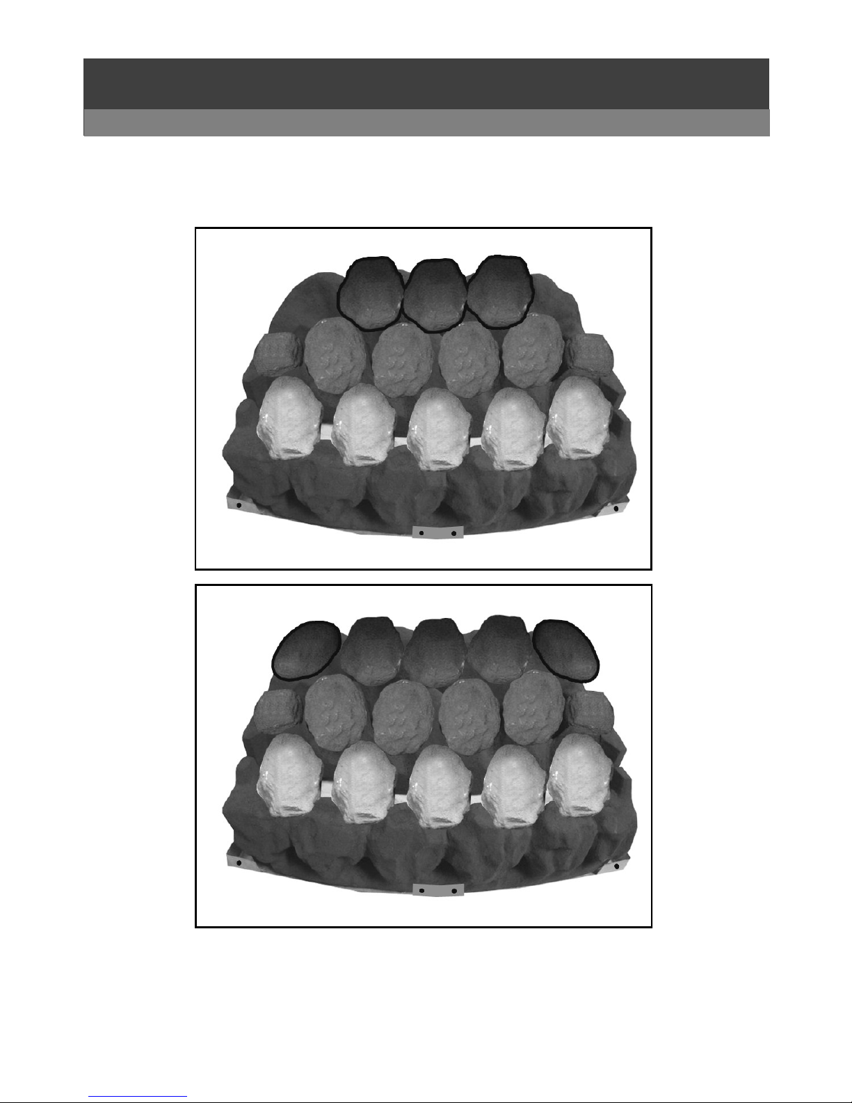
Take 4 of the large coals and position them as shown in Fig. 9 below.
Take the two small coals and position them as shown in Fig. 10 below.
Fig. 7
Fig. 9
8
Fig. 10
APPLIANCE INSTALLATION
Take 3 of the large coals and position them as shown in Fig. 11 below. Take the remaining two
medium coals and position them as shown in Fig. 12 below.
Only use the coals that are supplied with this appliance. If replacement coals are required, use
only a full genuine replacement set.
Fig. 11
9
Fig. 12

APPLIANCE INSTALLATION
FIRE FRONT
This appliance can be used with several different Vision Fires frets.
Any fret to be used must conform to the following dimensions (Fig. 13).
LIGHTING THE APPLIANCE
Open the gas isolation valve.
Push the control knob and turn fully anti clockwise to the position marked ‘P’ for Pilot. Hold the
control knob here until the pilot lights. Hold for a further 10 seconds to allow a stable flame.
Release the control knob and turn anti clockwise to the ‘HI’ position to ignite the main burner.
Turn the control knob clockwise to the ‘LO’ position to switch the fire to its minimum heat setting.
Push the control knob and turn clockwise to the ‘P’ position to extinguish the main burner while
leaving the pilot flame alight.
Push the control knob and turn fully clockwise to the ‘O’ position to extinguish the pilot flame. The
appliance is now turned off.
10
Fig. 13
MINIMUM OPEN AREA OF
FRET = 11,000mm²
MINIMUM OPEN AREA OF
ASH PAN COVER = 3,300mm²
MAX
HEIGHT
220MM
MINIMUM OPEN TOTAL OPEN AREA OF FRET
& ASH PAN COVER COMBINED = 16,000mm²
Table des matières
Autres manuels Vision Cheminée intérieure

Vision
Vision Ezi-Slide V150 B Instructions de montage

Vision
Vision E-line solus VS220 Manuel utilisateur

Vision
Vision V350B Instructions de montage

Vision
Vision Trimline Series Manuel utilisateur

Vision
Vision e-line SOLUS VS75 Manuel utilisateur

Vision
Vision V250 A Instructions de montage

Vision
Vision V1/200/A Instructions de montage

Vision
Vision V2/100/A Instructions de montage


