Vision Audio Visual TECHCONNECT TC-MATRIX Manuel utilisateur

1
TC-MATRIX_manual_en.doc
TECHCONNECT TC-MATRIX
OWNERS MANUAL
www.visionaudiovisual.com/techconnect/tc-matrix/

2
TC-MATRIX_manual_en.doc
DECLARATION OF CONFORMITY
Where applicable Vision products are certified and comply with all known local regulations to a
‘CB Certification’ standard. Vision commits to ensure all products are fully compliant with all
applicable certification standards for sale in the EU and other participating countries.
The product described in this owner manual is in compliance with RoHS (EU directive
2002/95/EC), and WEEE (EU directive 2002/96/EC) standards. This product should be returned
to the place of purchase at the end of its useful life for recycling.
WARNINGS
CAUTION: TO REDUCE THE RISK OF ELECTRIC SHOCK DO NOT REMOVE COVER (OR
BACK). NO USER-SERVICEABLE PARTS INSIDE. REFER SERVICING TO QUALIFIED
SERVICE PERSONNEL.
The lightning flash with arrowhead symbol, within an equilateral triangle, is intended to alert the
user to the presence of uninsulated “dangerous voltage” within the product’s enclosure that may be
of sufficient magnitude to constitute a risk of electric shock to persons.
The exclamation point within an equilateral triangle, is intended to alert the user to the presence of
important operating and maintenance (servicing) instructions in the literature accompanying the
appliance.
WARNING: TO REDUCE THE RISK OF FIRE OR ELECTRIC SHOCK, DO NOT EXPOSE
THIS APPLIANCE TO RAIN OR MOISTURE.
All products are designed and imported into the EU by ‘Vision’ who is wholly owned by ‘Azlan
Logistics Ltd.’, Registered in England Nr. 04625566 at Lion House, 4 Pioneer Business Park,
Clifton Moor, York, YO30 4GH. WEEE Registration: GD0046SY
DECLARATION OF ORIGIN
All Vision products are made in the People’s Republic of China (PRC).

3
TC-MATRIX_manual_en.doc
USE ONLY DOMESTIC AC OUTLETS
Connecting the unit to an outlet supplying a higher voltage may create a fire hazard.
HANDLE THE POWER CORD WITH CARE
Do not disconnect the plug from the AC outlet by pulling the cord; always pull the plug itself.
Pulling the cord may damage it. If you do not intend to use your unit for any considerable
length of time, unplug the unit. Do not place furniture or other heavy objects on the cord, and
try to avoid dropping heavy objects on it. Do not tie a knot in the power cord. Not only could
the cord be damaged, but a short circuit could also be caused with a consequent fire hazard.
PLACE OF INSTALLATION
Avoid installing this product under the following conditions:
• Moist or humid places
• Places exposed to direct sunlight or close to heating equipment
• Extremely cold locations
• Places subject to excessive vibration or dust
• Poorly ventilated places
Do not expose this product to dripping or splashing. DO NOT PLACE OBJECTS FILLED WITH
LIQUIDS ON OR NEAR THIS PRODUCT!
MOVING THE UNIT
Before moving the unit, be sure to pull out the power cord from the AC outlet and disconnect
the interconnection cords with other units.
WARNING SIGNS
If you detect an abnormal smell or smoke, turn this product off immediately and unplug the
power cord. Contact your reseller or Vision.
PACKAGING
Save all packing material. It is essential for shipping in the event the unit ever needs repair.
IF ORIGINAL PACKAGING IS NOT USED TO RETURN THE UNIT TO THE SERVICE CENTRE,
DAMAGE IN TRANSIT WILL NOT BE COVERED BY WARRANTY.

4
TC-MATRIX_manual_en.doc
TRANSMITTER
1. IR receiver (to switch Matrix channel, not for IR passthrough)
2. Standby indicator
3. Channel adjust button
4. Channel display (each Tx in system must be set to different channel)
5. Channel adjust button
1. 5V 3A Power input (note device cannot run on PoE)
2. Data transmission indicator
a. Slow flashing; establishing connection
b. Fast flashing; successfully connected and transmitting data
3. CAT5e/6 Output
4. Connection indicator; if no light then not connected to Rx
5. IR blaster minijack socket (plug IR blaster in here)
6. HDMI Input
7. Reset/restart button
1
2
3
1
5
4
2
3
4
5
6
7

5
TC-MATRIX_manual_en.doc
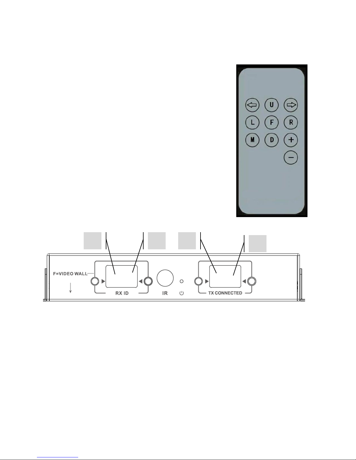
RECEIVER
1. Channel adjust button
2. Channel display (each Rx in system must be set to different channel)
3. Channel adjust button
4. IR receiver (to switch Matrix channel, not for IR passthrough)
5. Standby indicator
6. TX Channel adjust button
7. TX Channel display (determines which source this Rx will display)
8. TX Channel adjust button
1. 5V 3A Power input (note device cannot run on PoE)
2. Data transmission indicator
a. Slow flashing; establishing connection
b. Fast flashing; successfully connected and transmitting data
3. CAT5e/6 Input
4. Connection indicator; if no light then not connected to Tx
5. IR Receiver minijack socket (plug IR receiver in here)
6. HDMI Output
7. Reset/restart button
1
2
5
8
7
6
3
4
9
1
2
3
4
5
6
7

6
TC-MATRIX_manual_en.doc
FACTORY RESET
1/ Hold the two buttons circled at the same time until 00 is displayed
2/ Disconnect power
3/ Wait 3 seconds
4/ Reconnect power
7
TC-MATRIX_manual_en.doc
REMOTE CONTROL
M – Normal Mode
F – Video Wall Mode
Video Wall related functions:
L – Left
R – Right
U – Up
D – Down
(See Video Wall section for more information)
Left Arrow / Right Arrow
Selects LCD to adjust. LCD will start flashing:
+ / -
Once LCD is flashing, use these buttons to adjust up or down.
1
2
3
4

8
TC-MATRIX_manual_en.doc
SETUP – POINT TO POINT
It is not necessary to run the signal through a network switch. To use as an HDMI extender:
1. CONNECT TX TO RX Use a CAT6 cable to link a Tx directly to an Rx. The CAT6 cable must
be wired using normal IEEE-568B standard. It can be UTP or STP. Maximum length: 120
metres (394ft).
2. SET “TX CONNECTED” CHANNEL ON RX to match the channel on the Tx.

9
TC-MATRIX_manual_en.doc
SETUP – OVER NETWORK
This product uses Multicasting which is what allows one transmitter to send to many receivers.
Multicasting changes the way a network behaves.
VERY IMPORTANT:To use this product IGMP snooping MUST be activated on the network
switch. This is what allows multicasting. IGMP snooping can only be activated on a “layer-3”
managed switch.
Consider Netgear’s M4300-28 (24 port) or M4300-52 (48 port) as they are pre-configured for AV
Applications.
1. TURN IGMP SNOOPING ON You must use a managed switch. The network administrator
needs to go to the switch settings page in their browser and activate it.

10
TC-MATRIX_manual_en.doc
2. CONNECT ALL TX AND RX DEVICES TO NETWORK All devices must be on same subnet.
Microwave extenders may not have enough bandwidth to support this product which uses
up to 24Mbps transmitting 4K 60 Hz video
3. CONNECT SOURCES TO TX AND DISPLAYS TO RX One Tx for each source, one Rx for each
display. Uses proprietary encoding and cannot decode a stream from another product or
VLC.
4. SET CHANNEL ID ON ALL DEVICES
a. All Tx should be on different channels.
b. All Rx should be on different channels.
5. SET “TX CONNECTED” CHANNEL ON RECEIVERS The source connected to the Tx selected
will show on the display. Allow a few seconds for the HDCP handshake.
Set to Forwarding
Table des matières
Langues :


