Vishay G4 Manuel utilisateur

G4 Multi Channel
Weighing Instrument
Program version 1.7.0.0
Technical Manual
PM/DT/HE types
GB


1. Introduction
General ............................................1-1
Functions ..........................................1-2
Maintenance .....................................1-4
Safety information ............................1-4
Technical data ..................................1-5
Ordering information ......................1-12
2. Installation
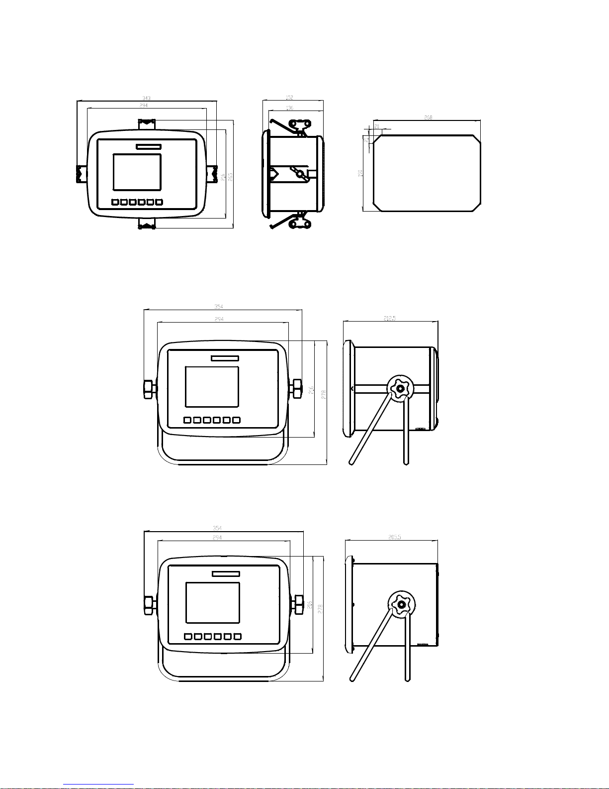
Mechanical installation .....................2-1
Electrical installation .........................2-2
CPU unit............................................2-3
DC SUPPLY .....................................2-5
AC SUPPLY .....................................2-6
WF IN, WF IN2 and HS WF2 ...........2-7
AOUT1 and AOUT4 .......................2-10
DIO8 ...............................................2-11
Profibus-DP Fieldbus Adaptor ........2-12
DeviceNet Fieldbus Adaptor ..........2-14
Front panel .....................................2-16
3. Set-up
General ............................................3-1
Graphical touch display ....................3-3
Menu structure .................................3-6
Parameters .......................................3-9
Program options .............................3-46
4. Calibration
General ............................................4-1
Common parameters .......................4-2
Data sheet calibration ......................4-4
Table calibration ...............................4-5
Deadweight calibration .....................4-5
5. Operation
General ............................................5-1
Power supply ....................................5-1
Power-up sequence .........................5-1
Display alt. by normal operation .......5-2
Security locks ...................................5-4
Taring ...............................................5-5
Gross/Net operation .........................5-6
Zero setting ......................................5-6
Zero-track./Auto. zero setting ...........5-7
Motion ...............................................5-7
Weight printing .................................5-8
Batch report printing ........................5-9
Main menu .......................................5-9
Level supervision ...........................5-11
Setpoint function ............................5-12
Use of inputs and outputs ..............5-13
Filter function .................................5-13
Flow rate ........................................5-15
6. Communication
General ............................................6-1
Serial interface..................................6-1
Modbus RTU Slave .........................6-1
Modbus TCP Slave ..........................6-2
External I/O.......................................6-3
Ftp Server.........................................6-4
Modbus protocol ..............................6-4
Fieldbus interface ...........................6-32
Weight printing................................6-46
7. Remote Access
General ............................................7-1
Browser requirements ......................7-1
Using the Remote Access ...............7-2
Security.............................................7-2
Remote Access Login and Logout ...7-3
Remote / Local Access.....................7-5
Remote Set-up..................................7-6
Remote Access Maintenance.........7-10
Instrument Restart..........................7-18
8. Maintenance
General ............................................8-1
Diagnostics.......................................8-1
File handling ....................................8-6
Create Backup .................................8-6
Restore Backup ...............................8-7
Set Default........................................8-7
Program Upgrade.............................8-7
Instrument Restart............................8-8
9. Troubleshooting
General.............................................9-1
Error codes ......................................9-1
Appendix
Declaration of Conformity.............App.1
Contents

Technical Manual
PRECAUTIONS
READ this manual BEFORE operating or servicing this instrument.
FOLLOW these instructions carefully.
SAVE this manual for future reference.
!
DO NOT allow untrained personnel to operate,
clean, inspect, maintain, service, or tamper with
this instrument.
INTENDED USE
The G4 Instrument family are multi channel measuring and control devices intended for
industrial systems. Its basic function is to convert the signals from transducers to useful
information. Transducer excitation is included as well as parameter controlled signal
processing, indication of output levels, error supervision and operation of optional
external equipment.
The instrument supports several types of communication interfaces. The instruments
are modular and can be equipped with different types of I/O units. There are transducer
interface modules, digital and analog input/output modules.
WARNING
Only permit qualified personnel to install and service this instrument.
Exercise care when making checks, tests and adjustments
that must be made with power on.
Failing to observe these precautions can result in bodily harm.

G4 Multi Channel Weighing Instrument
1-1
1. Introduction
General
The G4 Instrument is a high performance multi channel weight indicator intended for
industrial systems.
Its basic function is to convert the signals from strain gauge transducers to useful
weight information. Transducer excitation is included as well as parameter controlled
signal processing, indication of output levels, error supervision and operation of
optional external equipment. The instrument can be equipped with up to 8
synchronized weighing channels.
The instrument is modular and can be equipped with different types of I/O units to
match the demands in the specific applications. There are strain gauge transducer
interface modules, a digital input/output module, and analog output modules.
Internal solid-state outputs in the instrument can be used for output functions from level
supervision, setpoints, etc. or ‘In process’ indication, reporting the operating status of
the G4 Instrument.
The CPU unit in the instrument has several communication interfaces. It has two serial
communication ports, an Ethernet port, an USB port and a fieldbus slot.
Several G4 Instruments can be controlled from a master computer or PLC.
Serial communication interfaces are RS-485 and RS-232 for communication with a
computer/PLC (using Modbus RTU protocol) or for transmitting print out data to a
connected printer. The Ethernet interface is using Modbus TCP and the optional
fieldbus interface uses Profibus or DeviceNet.
It is possible to access the instrument, set-up and maintenance functions, remotely
over the Ethernet connection using a Web Browser on a connected PC.
In the Weighing program there are two program options available, one is the Flow Rate
program option and the other is the Scale Batching program option. By entering its
option code a program option is enabled. The option code can be purchased from your
supplier.
It is possible to load new software into the instrument using the USB port.
All functions in the G4 Instrument are controlled by set-up parameters. Setting of
parameter values can be performed with keys and/or graphical touch display on the
front panel.
24 V DC or 110/230 V AC powers the G4 Instrument. All input and output signals
are galvanically isolated from the power supply by operational insulation.
CPU
unit
I/O
unit
1
I/O
unit
2
I/O
unit
3
I/O
unit
4
I/O
unit
5
I/O
unit
6
Power
supply
unit
Backplane
Graphic color
display with
touch interface
Enclosure & mounting accessories
Operator panel
Key
pad
unit
Block structure of a G4 Instrument

Technical Manual
1-2
Functions
Measurement with strain gauge transducers.
Both excitation voltage and output signal are measured at the transducer to avoid
influence from voltage drop in the connection cable. Excitation to the transducer, from
the G4 Instrument is provided over separate wires.
A shielded 6-wire cable must be used to connect a distant transducer to the instrument.
A/D conversion.
The analog signals from the transducer are converted to digital form and filtered
to give an internal transducer signal with high resolution.
Calculation.
The transducer excitation and signal values are combined to form an internal
transducer signal, representing the load on the transducer. Influenced by calibration
data, this signal is converted to a digital measurement value, the weight value, which
can be presented at the local display window and at external equipment.
Error supervision.
As long as the error supervision detects no error, the signal ‘In process’ is present
but if an error is detected, ‘In process’ will be off and a specific error message will be
displayed. ‘In process’ can be set to control any digital output. Note that there are
weighing channel specific and instrument specific error detection.
Levels.
32 level comparators in the instrument can be set to switch at defined signal levels with
any selected hystereses added, meaning that the switch level can be different for
increasing and decreasing signal. Output signals from these comparators are available
on the serial communication. The level comparator outputs can also be set to control
digital outputs from the instrument.
Communication.
The G4 Instrument utilizes the serial interface, Ethernet and a fieldbus interface for
communication with control computer. The serial interface consists of a RS-232
(COM1) connection and a RS-485/RS-422 (COM2) connection. COM2 can be used
with 2- or 4-wire connection.
Weight values, level status, error status etc. can be collected and commands given
through the communication interfaces. Modbus RTU protocol is used for the serial
interfaces and Modbus TCP for the Ethernet connection. For the optional fieldbus
interface Profibus or DeviceNet can be used.
The serial interfaces can also be used to connect a printer for printing of weight and/or
flow rate values etc. If the Scale Batching Program Option is enabled it is possible to
print batching reports.

G4 Multi Channel Weighing Instrument
1-3
Instrument modes.
In normal operation mode the G4 Instrument is presenting the measurement values on
the front panel graphical display. One or more weighing channels can be shown
simultaneously. The user can configure the display via set-up parameters.
During parameter set-up the instrument will continue normal operation. However if
hardware set-up parameters have been changed the instrument will be restarted.
The operator will always be notified before the instrument is restarted.
Parameter setting.
In the instrument all operating functions are controlled by set-up parameters with
numerical values, string values, or pre-selected values from a list of alternatives.
Parameter set-up is performed by the keys at the front panel of the instrument and/or
by using the buttons displayed on the touch display.
Presentation.
The instrument can present measured or calculated values, status of levels, parameter
settings etc. at the front panel. An extensive system of menus gives the possibility to
present various information about the instrument.
Measured or calculated values, status of levels and so on, can be transferred to
external equipment via the different communication interfaces (some are optional).
Scale Batching program option.
There is a batching function within the instrument, which is enabled with an option
code, which can be bought from the instrument supplier. The batching option gives the
possibility to perform individual batching with each scale. See the separate ‘Scale
Batching Program Option’ ‘Technical Manual Supplement’ available for the batching
option.
Flow Rate program option.
With the Flow Rate program option enabled the instrument can calculate the flow rate
based on the weight. The flow rate is calculated and set-up individually for each scale.
Flow rate can be shown on the display, sent to (optional) analog outputs and read
through any of the available communication alternatives in the instrument. An option
code is required to enable this program option. See the description of the flow rate
calculation in this manual.
Remote Access.
It is possible to access the instrument through the Ethernet connection. Using a Web
Browser on the connected PC most set-up and maintenance functions are available on
the PC. This possibility will simplify commissioning and service. It will make it possible
to access instruments from outside the local network (internet) providing the network
allow this.

Technical Manual
1-4
Maintenance
The G4 instrument needs no maintenance, performed by the end-user. Any service
or repair work must be performed by qualified personnel.
Contact your supplier.
Cleaning
Before cleaning the G4, break the power connection to the instrument.
Use a soft cloth to clean the exterior of the instrument. For cleaning
the instrument front panel, a soft, damp, cloth may be used.
Safety information
Utilization.
Before connecting power to the instrument, check that all fixation screws
at the modules are tightened so that the instruments functional grounding
by the housing is maintained.
The instrument may only be utilized for the measurement and control functions,
described in this Technical Manual. It is especially important to adhere to the load limits
of the input/output connectors. We accept no responsibility for any damage arising from
improper operation.
Any changes to the instrument, which causes any function changes, may only be
carried out by the manufacturer, or after discussion with and permission by the
manufacturer.
Meaning of symbols, used in this manual
Direct current.
Alternating current.
!Caution, risk of danger. Documentation needs to be consulted.

G4 Multi Channel Weighing Instrument
1-5
Technical data
Enclosure
types PM - Panel mount DT – Desktop HE – Harsh
Environment
Enclosure
design Aluminium housing,
plastic panel Aluminium housing,
plastic panel Stainless steel housing,
plastic panel
Dimensions See figure
Panel thickness:
2 – 25 mm
See figure See figure
Strain relief — 6 pcs. for cable dia.
4.3 to 11.4 mm 6 pcs. for cable dia.
4.3 to 11.4 mm
Display Color TFT LCD screen with backlighting, 5.7” 320x240 pixels
Keyboard Touch screen and 34 membrane keys
Environmental
Temperature
range
Rated performance: -10 to +50 C
Storage: -25 to +85 C
Relative
humidity Max. 85% up to 40°C, decreasing linear to 50% at 50°C
Rated pollution Pollution degree 2 Pollution degree 3 Pollution degree 3
Protection IP65 (panel), indoor use IP65, indoor use.
Rated for wet locations IP65, indoor use.
Rated for wet locations
Altitude Up to 2000 m
EMC, RF CE (Industrial), OIML

Technical Manual
1-6
PM -Panel mount enclosure outlines and panel cutout.
DT -Desktop enclosure outlines
HE - Harsh environment enclosure outlines
Autres manuels pour G4
5
Ce manuel convient aux modèles suivants
3
Table des matières
Autres manuels Vishay Accessoires

Vishay
Vishay TSSP770 Series Manuel utilisateur

Vishay
Vishay TSSP96038TR Manuel utilisateur

Vishay
Vishay PM 1155 Manuel utilisateur

Vishay
Vishay TSSP60 Series Manuel utilisateur

Vishay
Vishay VT400 Manuel utilisateur

Vishay
Vishay VCNL3020 Manuel utilisateur

Vishay
Vishay TSSP60 Series Manuel utilisateur

Vishay
Vishay TSSP770 Series Manuel utilisateur

Vishay
Vishay G4 Mode d'emploi

Vishay
Vishay G4 Manuel utilisateur


