Viking Range 3 Series Manuel utilisateur

Installation
GUIDE
5 SERIES
VDWU524SS
VDWU524WSSS
FDWU524WS
FDWU524
3 SERIES
VDWU324SS
FDWU324
7 SERIES
VDWU724SS
FDWU724

INTRODUCTION ___________________________________________________________ 3
1. IMPORTANT SAFETY INSTRUCTIONS ______________________________________ 3
1.1 INSPECT THE DISHWASHER _____________________________________________ 4
2. TOOLS WHICH MAY BE NEEDED __________________________________________ 5
3. MATERIALS WHICH MAY BE NEEDED ______________________________________ 6
4. MATERIALS SUPPLIED___________________________________________________ 6
4.1 PARTS SUPPLIED ______________________________________________________ 6
4.2 MANUAL BAG __________________________________________________________ 6
4.3 DISHWASHER PARTS BAG 1 _____________________________________________ 6
4.4 DISHWASHER PARTS BAG 2 _____________________________________________ 6
4.5 PARTS ATTACHED TO THE REAR OF THE DISHWASHER______________________ 6
5. DISHWASHER SPECIFICATIONS ___________________________________________ 7
5.1 TECHNICAL FEATURES _________________________________________________ 7
6. ENCLOSURE PREPARATION ______________________________________________ 8
6.1 FOAM RUBBER INSTALLATION ___________________________________________ 8
6.2 ELECTRICAL PREPARATION _____________________________________________ 8
6.3 STEAM PROTECTIVE FOIL _______________________________________________ 9
6.4 INSTALLING THE SIDE PLUGS ____________________________________________ 10
6.5 INSTALLING THE SIDE TRIM______________________________________________ 10
7. CONNECTING THE WATER LINES__________________________________________ 11
7.1 PREPARING THE WATER CONNECTION____________________________________ 11
7.2 WATER CONNECTION___________________________________________________ 11
7.3 ADJUSTING THE HEIGHT ________________________________________________ 12
7.4 PLACEMENT OF DISHWASHER INTO OPENING _____________________________ 12
8. PREPARING THE CUSTOM DOOR__________________________________________ 13
8.1 INSTALLING THE CUSTOM DOOR _________________________________________ 15
9. SECURING TO THE CABINETRY ___________________________________________ 16
9.1 RE-ADJUSTING THE KICKPLATE __________________________________________ 16
9.2 SECURING WITH MOUNTING BRACKETS __________________________________ 16
9.3 SECURING TO THE CABINET_____________________________________________ 17
10. DRAIN HOSE CONNECTION, WATER SUPPLY & ELECTRICAL _________________ 18
10.1 DRAIN HOSE CONNECTION _____________________________________________ 18
10.2 DRAIN PREPARATION __________________________________________________ 18
10.3 DRAIN INSTALLATION __________________________________________________ 19
10.4 WATER LINE CONNECTION _____________________________________________ 20
10.5 ELECTRICAL CONNECTION _____________________________________________ 20
11. FINAL INSTALLATION __________________________________________________ 22
11.1 INSTALLING THE TOE KICK INSULATION AND TOE KICK _____________________ 22
12. INSTALLER CHECKLIST ________________________________________________ 24
13. TROUBLESHOOTING ___________________________________________________ 25
14. SERVICE INFORMATION ________________________________________________ 26
2USA
3USA
To prevent accidents, which could
cause serious injury or death, as
well as machine damage read these
instructions before installation and / or
use.
INTRODUCTION
Please read this installation manual
and particularly the safety instructions
completely and carefully. They will save you
time and effort and help to ensure optimum
dishwasher performance.
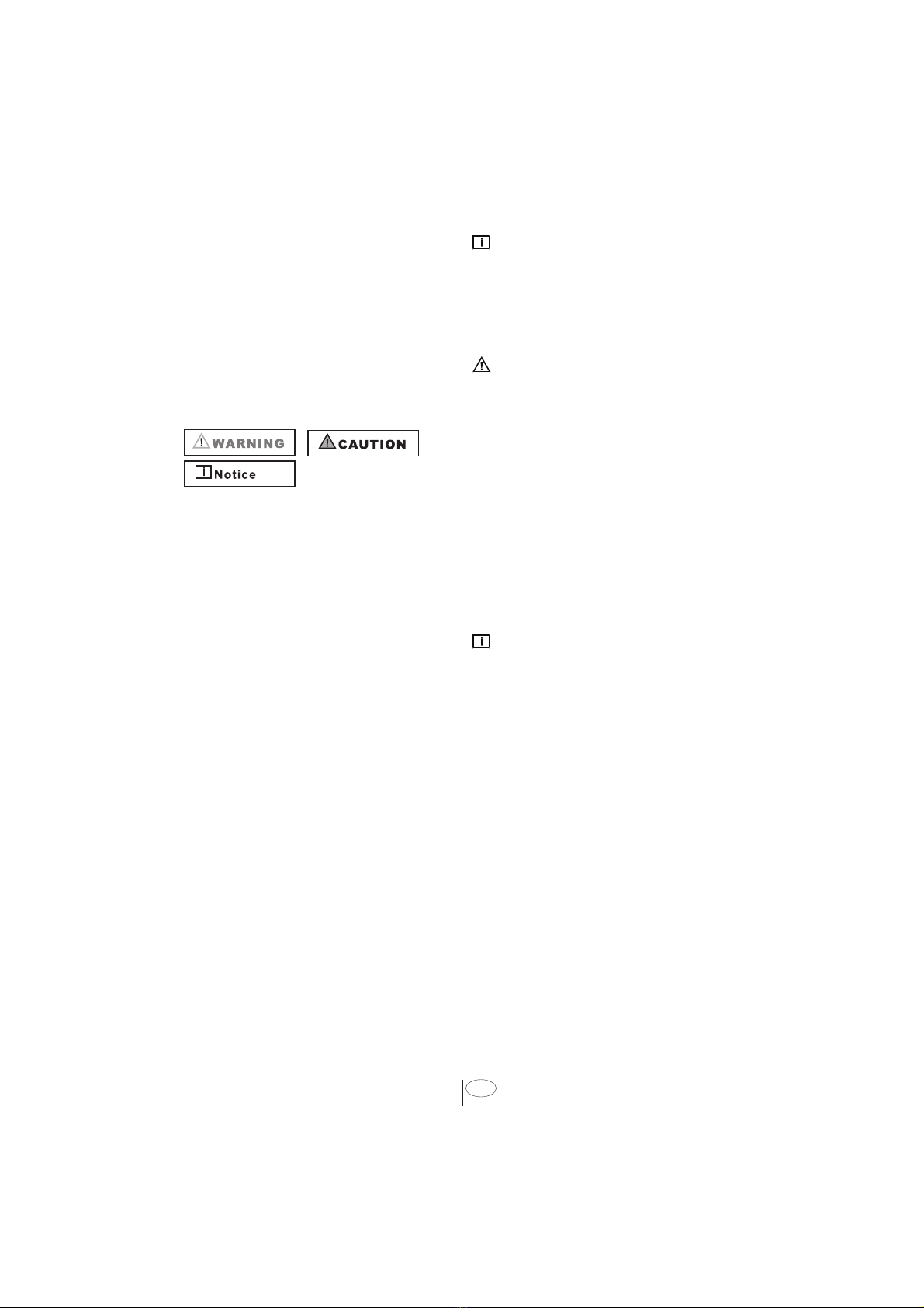
Be sure to observe all listed warnings and
cautions. Look particularly for the icons with
exclamation marks inside. The information
icon also will provide important references.
WARNING:
Indicates a potentially hazardous situation
which, if not avoided, could result in death
or serious injury.
CAUTION:
Indicates a potentially hazardous situation
which, if not avoided, may result in injury.
It may also be used to alert against unsafe
practices.
NOTICE:
Indicates a potentially hazardous situation
which, if not avoided, may result in damage
to the dishwasher, the table-ware, the
equipment or the environment.
1. IMPORTANT SAFETY
INSTRUCTIONS
In addition to these instructions, the
dishwasher shall be installed:
• In accordance with all local codes or, in
absence of a local code,
• In the United States, with the National
Electric Code,
• In Canada, with the Canadian Electric
Code C22.1-latestedition/Provincial and
Municipal codes and/or local codes.
NOTICE :
Read these installation instructions
completely before installing and follow
them carefully. Save these installation
instructions and pass them on to any future
user.
WARNING
When installing the dishwasher, follow
basic precautions, including the
following:
• The dishwasher could only be converted
from cord-connected to permanently
connected by an authorized service
representative. (If needed contact your
dealer to schedule an authorized service
agent for conversion with an appropriate
conversion kit)
• Installation and repair should be
performed by a qualified installer.
Work by unqualified persons could be
dangerous and may void the warranty.
NOTICE :
The dishwasher should be installed by
an insured licensed plumber, contractor
or trained installer. Installation performed
by persons other than this could result in
improper installation and property damage.
• Do not operate the appliance if damaged,
malfunctioning, partially disassembled or
if it has missing or broken parts.
• Also follow the safety instructions of the
user manual.
• To reduce the risk of electric shock, fire,
or injury to persons, the installer must
ensure that the dishwasher is completely
enclosed at the time of installation.
• Only connect the dishwasher to the
power supply when all installation and
plumbing work is complete.
• If the dishwasher is installed in a location
that experiences freezing temperatures
(e.g. in a vacation home, cabin, etc.),
you mustdrain all the water from the
dishwasher’s interior. Water system
ruptures that occur as a result of freezing
are not covered by warranty.

4USA
• Dishwasher mustbe secured to adjacent
cabinetry using the brackets provided.
Failure to do this may cause damage to
property or bodily injury.
• Connect to a properly rated, protected
and sized power supply circuit to avoid
electrical overload. The dishwasher is
designed for an electrical supply of 120 V
(volts), 60 Hz (hertz), AC, connected to a
dishwasher-dedicated, properly grounded
electrical circuit with a fuse or breakers
rated for 15 amperes. Electrical supply
conductors shall be a minimum of # 16
AWG copper wire rated at 75 °C (167
°F) or higher. These requirements must
be met to prevent injury and machine
damage. Consult a qualified electrician if
in doubt.
• Do not use any extension cord or
portable outlet device to connect the
dishwasher to a power supply.
• Ensure that any plastic wrappings, bags,
small pieces etc. are disposed of safely
and kept out of the reach of children.
Danger of suffocation!
• Remove the door to the washing
compartment when removing an old
dishwasher from service or discarding it.
Ensure that the appliance presents no
danger to children while being stored for
disposal.
• Old appliances may contain materials
that can be recycled. Please contact
your local recycling authority about the
possibility of recycling these materials.
NOTICE :
• The dishwasher drain hose mustbe
installed with a drain loop at least28”
(710mm) offthe cabinet floor; otherwise
the dishwasher may not drain properly.
• This dishwasher is intended for
residential use only, and should not be
used in commercial establishments.
• New installation - If the dishwasher is a
new installation, mostof the work must
be done before the dishwasher is moved
into place.
• Replacement - If the dishwasher is
replacing another dishwasher, check
the existing dishwasher connections for
compatibility with the new dishwasher,
and replace parts as necessary.
1.1 INSPECT THE DISHWASHER
After unpacking the dishwasher and prior
to installation, thoroughly inspect the
dishwasher for possible freight or cosmetic
damage. Report any damage immediately.
NOTICE :
• Cosmetic defects mustbe reported within
10 days of installation.
• Do not discard any bags or items that
come with the original package until
after the entire installation has been
completed.

5USA
2. TOOLS WHICH MAY BE NEEDED
Flat head Screwdriver
3. MATERIALS WHICH MAY BE NEEDED
(Additional materials may be required to comply with local codes)
Hot Water Supply Line - Minimum 3/8” O.D. copper tubing or metal braided
dishwasher supply line.
Elbow with 3/4” FHT(female threaded) for dishwasher side, and sized to fit
your water supply line (copper tubing/compression fitting, or braided hose)
on the other side. Dishwasher connection is 3/4" male.
UL listed conduit connector or strain relief.
Teflon tape or other pipe thread compound to seal plumbing connections.
Shut-off valve and fittings appropriate for hot water supply line (copper
tubing/compression fitting, or braided hose).
Silicone
Glue
Dishwasher Discharge Hose Adaptor

6USA
4. MATERIALS SUPPLIED
4.1 PARTS SUPPLIED
Parts for your dishwasher will
come in several plastic bags.
Check your parts bags shown
to make sure you have all the
parts as listed to the left.
4.2 MANUAL BAG
The dishwasher comes with a
manual bag containing:
• User manual,
• Installation manual
4.3 DISHWASHER
PARTS BAG 1
This dishwasher bag comes
with the following parts:
a. Side Trim Strips (Left)
b. Side Trim Strips (Right)
d. Screws Ø 1/8” x 5/8” (Ø
3.5 mm x 14 mm)
e. Mounting Bracket Left
f. Mounting Bracket Right
h. Screw Clamp
k. Toe Kick Bracket - Left
l. Toe Kick Bracket – Right
n. Custom Door Plug
o. Custom Door Screw
p. Toe Kick
s. Template
t. Hook and loop fastener
v. Side spacer
z. Steam Protection Foil
4.4 DISHWASHER
PARTS BAG 2
(SELECT MODELS)
In addition to the manual bag
and the dishwasher parts bag
(dishwasher models which
can accept a wooden kitchen
door) also come with a door
panel installation kit which
contains:
y. Screws 4mm x 36 mm =
3/16th x 1-7/16th
4.5 PARTS ATTACHED
TO THE REAR OF THE
DISHWASHER
a. Side Trim Strips (Left)
b. Side Trim Strips (Right)
x6

7USA
5. DISHWASHER SPECIFICATIONS
22-/”
(570 mm)
5.1 TECHNICAL FEATURES
Permissible water pressure 4.35 - 145 psi (0.3 - 10 bars)
Electrical connection 120 V (volts), 12 A (amps), 60Hz (hertz)
Total power 1400 W (watts)
Heater power 1100 W (watts)
NOTICE :
Because we continually strive to improve our products, we may change our specifications
and design without prior notice.
This device corresponds to the following directives:
UL 749 Household Dishwasher directive.

8USA
6.2 ELECTRICAL PREPARATION
WARNING
The dishwasher is designed for an electrical supply of 120 V, 60 Hz, AC, connected
to a dishwasher-dedicated, properly grounded electrical circuit with a fuse or
breaker rated for 15 amperes.
6. ENCLOSURE PREPARATION
6.1 FOAM RUBBER INSTALLATION
Open the foam insulation tape and follow the instructions in it.
This step is not imperative, but it will help you improve your soundproofing

9USA
6.3 STEAM PROTECTION FOIL
Steam will form inside the dishwasher during operation. At the end of the cycle, when the
dishwasher door is opened, it is required to use a steam protection foil to prevent any
steam from collecting on the underside of the counter top.
FITTING THE PROTECTION FOIL
Before applying the steam protection foil to the
underside of the countertop, clean the area with
a damp cloth (as shown in Figure A). Once the
area dries, apply the steam protection foil.
CAUTION
Steam protection foil mustbe applied
where the steam escapes when door is
firstopened. Failure to install the steam
protection foil during installation can lead to
damage to the cabinets and countertop.
The steam protection
foil will be applied at the
location where the hot
steam escapes when you
firstopen the door (as
shown in Figure B).

6.5 INSTALLING THE SIDE TRIM
Make sure you are using the correct side of the trim. The flexible material should be facing
forward (Figure A)
Remove the adhesive tape (Figure B)
Place the trim strips on the front edge of the side walls so that the notches align with the
side plugs (Figure C).
A
C
B
x1 x1
Install the 4 spacers (v) into the
openings on each side of the
dishwasher as shown.
6.4 INSTALLING THE SIDE PLUGS
10 FR
NOTE: Side trim may or may not have notches already cut. If there are no notches, you
will need to measure and cut notches as shown in diagram below to match side plug
locations before installing.
Autres manuels pour 3 Series
11
Ce manuel convient aux modèles suivants
10
Table des matières
Autres manuels Viking Range Lave-vaisselle

Viking Range
Viking Range Professional 450 Series Manuel utilisateur

Viking Range
Viking Range VDW302 Manuel utilisateur

Viking Range
Viking Range 1 Series Manuel utilisateur

Viking Range
Viking Range 5 Series VGC Manuel utilisateur

Viking Range
Viking Range VDWU524SS Manuel utilisateur

Viking Range
Viking Range 451 Series Manuel utilisateur

Viking Range
Viking Range Professional & Designer 325E Series Manuel utilisateur

Viking Range
Viking Range 301 Series Manuel utilisateur

Viking Range
Viking Range 3 Series Manuel utilisateur

Viking Range
Viking Range 301 Series Manuel utilisateur


