DANGER
BEFORE OPENING ANY PUMP LIQUID CHAMBER (PUMPING CHAMBER, RESERVOIR, RELIEF VALVE ADJUSTING
CAP FITTING ETC.) BE SURE:
1. THAT ANY PRESSURE IN CHAMBER HAS BEEN COMPLETELY VENTED THROUGH SUCTION OR DISCHARGE
LINES OR OTHER APPROPRIATE OPENINGS OR CONNECTIONS.
2. THAT THE DRIVING MEANS (MOTOR, TURBINE, ENGINE, ETC.) HAS BEEN “LOCKED OUT” OR MADE NON-
OPERATIONAL SO THAT IT CANNOT BE STARTED WHILE WORK IS BEING DONE ON PUMP.
3. THAT YOU KNOW WHAT LIQUID THE PUMP HAS BEEN HANDLING AND THE PRECAUTIONS NECESSARY TO
SAFELY HANDLE THE LIQUID. OBTAIN A MATERIAL SAFETY DATA SHEET (MSDS) FOR THE LIQUID TO BE
SURE THESE PRECAUTIONS ARE UNDERSTOOD.
FAILURE TO FOLLOW ABOVE LISTED PRECAUTIONARY MEASURES MAY RESULT IN SERIOUS INJURY OR DEATH.
ROTATION: Rotary gear pumps operate equally well in a clockwise or counterclockwise rotation. The shaft
rotation determines which port is suction and which is discharge. Port in area where pumping elements (gear
teeth) come out of mesh is suction port.
PRESSURE RELIEF VALVES:
1. Rotary gear pumps are positive displacement pumps and must be provided with some sort of pressure
protection. This may be a relief valve mounted directly on the pump, an inline pressure relief valve, a torque
limiting device or a rupture disk.
2. There are relief valve options available on those pump models designed to accept a
relief valve. Options may include a return to tank relief valve and a jacketed relief
valve. Pumps equipped with a jacketed head are not available with a relief valve.
3. If pump rotation is reversed during operation, pressure protection must be provided
on both sides of pump.
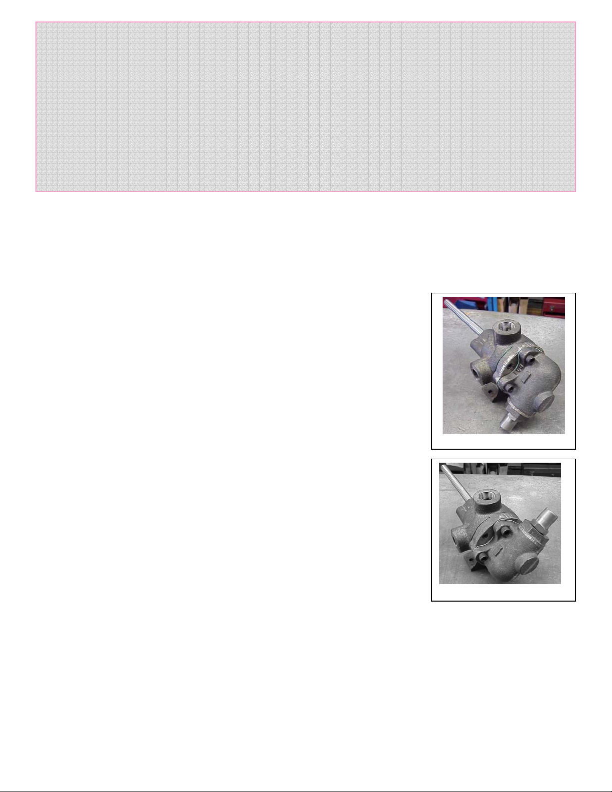
4. Relief valve bonnet must always point towards suction side of pump. If pump
rotation is reversed, remove pressure relief valve and turn end for end. Figures 2
and 3 show the 2 possible configurations, Figure 2 has side suction and top
discharge. Figure 3 has top suction and side discharge. The shaft turns in the
opposite direction on the second pump.
5. Pressure relief valves cannot be used to control pump flow or regulate discharge
pressure.
SPECIAL INFORMATION
SPECIAL MECHANICAL SEALS can be installed either next to rotor hub or behind the
bracket bushing.
Extra care must be taken in repair of pumps with mechanical seals. Read and follow all
special information supplied with pump.
MAINTENANCE
Series 32 pumps are designed for long, trouble-free service life under a wide variety of
application conditions with a minimum of maintenance. The points listed below will help
provide long service life.
LUBRICATION: External lubrication must be applied slowly with a handgun to all lubrication fittings every 500
hours of operation with multi-purpose grease. Do not over-grease. Applications involving very high or low
temperatures will require other types of lubrication. Consult factory with specific lubrication questions.
PACKING ADJUSTMENT: New packed pumps require initial packing adjustment to control leakage as packing
“runs in”. The adjustment should be made while the pump is operating with normal operating pressure on the
discharge of the pump. Make adjustments carefully and do not over-tighten packing gland. Evenly tighten the
gland fasteners until the leak is reduced to a very slow drip. If over tightened the packing will over heat, score the
shaft and reduce life. After initial adjustment, inspect periodically for increased leakage and re-adjust. Once the
gland has been tightened to the stuffing box, loosen the packing gland and add one ring to the stuffing box, then
adjust again. Refer to instructions under Disassembly, page 6, and Assembly, page 7, regarding repacking pump.
Figure 2
Figure 3
2