Viessmann VITOVENT 300 Mode d'emploi
VIESMANN
Service instructions
for contractors
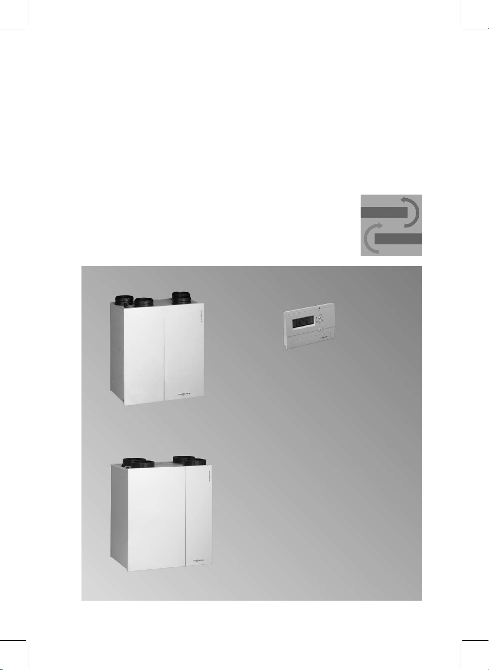
Vitovent 300
Domestic ventilation system with heat recovery
Air flow rate up to 180,300 and 400 m
3
/h
For applicability, see the last page
VITOVENT 300
5692 762 GB 3/2008 Please keep safe.

Please follow these safety instructions closely to prevent accidents and
material losses.
Safety instructions explained
Danger
This symbol warns against the
risk of injury.
!Please note
This symbol warns against the
risk of material losses and
environmental pollution.
Note
Details identified by the word "Note"
contain additional information.
Target group
These instructions are exclusively
designed for qualified personnel.
&Work on gas equipment must only
be carried out by a qualified gas fit-
ter.
&Work on electrical equipment must
only be carried out by a qualified
electrician.
&The system must be commissioned
by the system installer or a qualified
person authorised by the installer.
Regulations
Observe the following when working
on this system
&all legal instructions regarding the
prevention of accidents,
&all legal instructions regarding
environmental protection,
&the Code of Practice of relevant
trade associations,
&all current safety regulations as
defined by DIN, EN, DVGW, TRGI,
TRF, VDE and all locally applicable
standards.
If you smell gas
Danger
Escaping gas can lead to
explosions which may result in
serious injury.
&Never smoke. Prevent naked
flames and sparks. Never
switch lights or electrical
appliances ON or OFF.
&Close the gas shut-off valve.
&Open windows and doors.
&Remove all people from the
danger zone.
&Notify your gas or electricity
supplier from outside the
building.
&Shut off the electricity supply
to the building from a safe
place (outside the building).
If you smell flue gas
Danger
Flue gas can lead to life-threa-
tening poisoning.
&Shut down the heating sys-
tem.
&Ventilate the boiler room.
&Close all doors leading to the
living space.
Safety instructions
2
Safety instructions
5692 762 GB

Working on the system
&When using gas as fuel, also close
the main gas shut-off valve and
safeguard against unauthorised
reopening.
&Isolate the system from the power
supply and check that it is no longer
'live', e.g. by removing a separate
fuse or by means of a main isolator.
&Safeguard the system against
unauthorised reconnection.
!Please note
Electronic modules can be
damaged by electro-static dis-
charges.
Touch earthed objects, such as
heating or water pipes, to dis-
charge static loads.
Repair work
!Please note
Repairing components which
fulfil a safety function can com-
promise the safe operation of
your heating system.
Replace faulty components
only with original Viessmann
spare parts.
Ancillary components, spare and
wearing parts
!Please note
Spare and wearing parts which
have not been tested together
with the heating system can
compromise its function. Instal-
ling non-authorised compo-
nents and non-approved
modifications/conversion can
compromise safety and may
invalidate our warranty.
For replacements, use only ori-
ginal spare parts from
Viessmann or those which are
approved by Viessmann.
Safety instructions (cont.)
3
Safety instructions
5692 762 GB

Commissioning, inspection, maintenance
Steps –commissioning, inspection and maintenance .................................. 5
Further details regarding the individual steps .............................................. 6
Troubleshooting
Diagnosis at the remote control................................................................... 29
Remote control settings
Menu structure overview ............................................................................. 32
Remote control settings by contractors........................................................ 32
Components
Sensor resistance curve ............................................................................. 39
Fuses ......................................................................................................... 39
Connection and wiring diagram ............................................................... 40
Parts list .................................................................................................... 43
Commissioning/service reports
List of control parameters............................................................................ 47
Commissioning report................................................................................. 47
Commissioning report –example ................................................................ 48
Specification............................................................................................. 49
Certificates
Declaration of conformity ............................................................................ 50
Keyword index .......................................................................................... 51
Index
4
Index
5692 762 GB

For further information regarding the individual steps, see the page indicated
Commissioning steps
Inspection steps
Maintenance steps Page
!!!
•01. Pre-inspection of the system............................................ 6
••• 02. Starting the system .............................................................. 7
•03. Adjusting the air volume .................................................... 8
•04. Setting the language, time and date
(commissioning) ................................................................... 9
•05. Adjusting the ventilation apertures ............................... 10
•06. Measuring the air flow rates.............................................. 19
••• 07. Shutting down the system ................................................. 22
•08. Opening the appliance ........................................................ 23
•09. Countercurrent heat exchanger and filter, cleaning
or replacing ............................................................................. 24
• • 10. Cleaning the ventilation air and extract air device. . . 26
• • 11. Checking the condensate drain inside the
appliance .................................................................................. 26
•12. Installing the countercurrent heat exchanger............ 26
••• 13. Checking the tightness of electrical plug-in
connectors and cable grommets
•14. Cleaning the grease filter of the kitchen extract air
valve........................................................................................... 27
•15. Cleaning the ventilation air apertures and extract
air valves .................................................................................. 28
••• 16. Starting the system and checking its functions........ 28
Steps –commissioning, inspection and maintenance
5
Commissioning, inspection, maintenance
5692 762 GB

Pre-inspection of the system
Danger
Incorrect installation of the
ventilation system can lead to
injuries and equipment
damage.
Always observe the following
instructions.
Simultaneous operation with open flue combustion equipment
!Please note
If the pressure inside the instal-
lation room of the fireplace
drops more than 0.04 mbar,
flue gases may flow back into
the room.
In that case, the installation of
a pre-heater bank (accessory)
or a geothermal heat exchan-
ger is always required.
&Never operate this domestic ventila-
tion system together with open
flue combustion equipment (e.g.
open fireplaces or combustion
appliances for solid fuel). A
mechanical domestic ventilation
system and a combustion appliance
for solid fuel (fireplace) can be oper-
ated together if these combustion
systems are supplied with combus-
tion air via a dedicated air duct. This
should be agreed with the local fuel
gas inspector [where appropriate].
Doors to boiler rooms where the
combustion air supply is not inter-
connected with the living space,
must be airtight and must be kept
closed.
&If the domestic ventilation system is
to be operated together with the
open flue combustion appliance
(open flue gas fired boiler or fire-
place), no negative pressure must
be created inside the installation
room as a result of the operation of
the domestic ventilation system.
Both appliances must be mutually
interlocked (accessories, see tech-
nical guide). When using other
makes, ensure on-site interlocking.
&An air pressure or safety pressure
limiter (on-site) can be installed as a
further interlocking option. This
requires the installation of the auxili-
ary PCB (accessory). This inter-
rupts the power supply to the
installation room of the combustion
equipment and switches the appli-
ance off.
Further details regarding the individual steps
6
Commissioning, inspection, maintenance
5692 762 GB

Extractor hoods and expelled air clothes driers
&Extractors and expelled air clothes
drier must not be incorporated in the
ductwork of the ventilation system.
Design cooker hoods as recirculat-
ing or expelled air extractors. For
reasons of energy savings, we
recommend the installation of coo-
ker hoods as recirculating appli-
ances.
Note
The ventilation air required by extrac-
tors such as kitchen extractors and
expelled air clothes driers must be
allowed for and provided on site. A
window contact switch is recom-
mended.
System pressure
&We recommend the system is
checked for the following character-
istics, starting with the air inlet:
––Unobstructed cross-section of out-
side air inlet and expelled air out-
let.
––Sizing and routing of pipes
according to design.
––Correct equipment installation and
attachment of lines, silencers and
valves.
––Arrangement and accessibility of
cleaning apertures.
––Connection of the appliance to
pipework as flexible version.
––Correct condensate drainage and
proper insulation of lines in cold
areas.
Starting the system
1. Check that the power plug is
plugged into a standard socket with
its own fuse protection (230 V/
50 Hz).
Plug in the power plug if required.
2. Check the position of the program
selector at the remote control.
The rotary selector must not be set
to standby "9".
Set the program selector switch to
another position if required.
Operating instructions
Further details regarding the individual steps (cont.)
7
Commissioning, inspection, maintenance
5692 762 GB

Adjusting the air volume
The air flow rate of the Vitovent 300 is
preset at the factory to the following
values:
Version: 180 m
3
/h 300 m
3
/h 400 m
3
/h
Reduced mode:
(Display "1")
75 m
3
/h 100 m
3
/h 100 m
3
/h
Standard mode:
(Display "2"- basic air change)
100 m
3
/h 150 m
3
/h 200 m
3
/h
Demand-dependent mode:
(Display "3")
150 m
3
/h 225 m
3
/h 300 m
3
/h
These settings can be adjusted to suit
the local conditions.
For this observe that the setting for
reduced mode must always be lower
than the setting for standard mode,
which in turn must be lower than the
setting for the demand mode.
The air flow rate of the higher operat-
ing mode will be selected automati-
cally if one of these conditions is not
met during the setting process.
Note
The air flow rates that the Vitovent
can actually achieve are subject to
the layout of the air duct system and
the pressure drop (cleanliness) of the
filters.
To maintain the selected air volume
(on the ventilation and the extract air
sides) irrespective of the system pres-
sure drop, the speed of both fans is
automatically adapted.
Further details regarding the individual steps (cont.)
8
Commissioning, inspection, maintenance
5692 762 GB

Setting the language, time and date (commissioning)
Remote control
Note
During commissioning, an automatic
display prompts you to make the fol-
lowing adjustments in sequence: Lan-
guage, time and date.
Rotary selector Afor program selec-
tion can be set freely.
1. xw for "LANGUAGE", the word
"German" flashes.
2. dto confirm the selected lan-
guage; figure "12" (hour)
flashes.
3. xw to enter "HOUR",
"MINUTE", "YEAR",
"MONTH" and "DAY".
4. drespectively to confirm.
5. Start of the program to which the
rotary selector has already been
set.
For further functions and adjustments,
see from page 29 and parameter list
from page 33.
Operating instructions
Further details regarding the individual steps (cont.)
9
Commissioning, inspection, maintenance
5692 762 GB

Adjusting the ventilation apertures
Ventilation aperture for wall integration (DN 100)
1. Determine the width of the air inlet
using the intended flow rate and the
specified pressure drop from the
following diagram.
2. Adjust the air inlet in accordance
with the calculated aperture width.
ANumber of apertures
3. Record the actual value in the com-
missioning report.
Example:
Calculate the number of apertures at a
pressure drop of Δps= 20 Pa:
Air flow rate (acc.
to design):
qv= 27 m
3
/h
Number of aper-
tures:
6
Ventilation aperture for ceiling mounting (DN 100)
Note
&By twisting sector plate Bthe
direction of the fixed air outlet angle
of 180° can be determined (e.g.
installation near walls).
&Removing sector plate Blets the
air exit evenly at an angle of 360°
(e.g. installation at the centre of the
room).
Further details regarding the individual steps (cont.)
10
Commissioning, inspection, maintenance
5692 762 GB
Autres manuels pour VITOVENT 300
8
Table des matières
Autres manuels Viessmann Ventilateur

Viessmann
Viessmann VITOVENT 300 Mode d'emploi

Viessmann
Viessmann Vitovent 300-W Manuel utilisateur

Viessmann
Viessmann Tecto Refrigo CMC1 Manuel utilisateur

Viessmann
Viessmann VITOVENT 300 Guide de démarrage rapide

Viessmann
Viessmann Vitovent 300-W Guide rapide

Viessmann
Viessmann VITOVENT 300 Mode d'emploi

Viessmann
Viessmann Vitovent 200-C Guide rapide

Viessmann
Viessmann VitoAid Manuel utilisateur

Viessmann
Viessmann Vitodens 100-W WB1B Series Manuel utilisateur

Viessmann
Viessmann Vitovent 300-W Manuel utilisateur


