Viessmann VITODENS 200 Mode d’emploi

Operating Instructions and
User’s Information Manual
Cascade Control
Outdoor reset control for
up to four gas-fired wall-mounted
Vitodens 200, WB2-44 or -60 boilers
CASCADE CONTROL
Read and save these instructions
for future reference.
IMPORTANT
Certified as a component part
of Viessmann boilers only
Please file in Service Binder
5285 565 v1.3 11/2003

2
Safety, installation and warranty requirements
Please ensure that this manual is read and understood before commencing installation. Failure to comply with the issues listed be-
low and details printed in this manual can cause product/property damage,severe personal injury, and/or loss of life. Ensure all
requirements below are understood and fulfilled (including detailed information found in manual subsections).
HLicensed professional heating
contractor
The installation, adjustment, service,
and maintenance of this equipment
must be performed by a licensed pro-
fessional heating contractor.
"Please see sections
entitled “Safety” and
“Important Regulatory and
Installation Requirements”
in the Installation and
Start-up/Service Instructions.
HProduct documentation
Read all applicable documentation be-
fore commencing installation. Store
documentation near boiler in a readily
accessible location for reference in the
future by service personnel.
"For a listing of applicable
literature, please see
section entitled “Important
Regulatory and Installation
Requirements”
in the Installation and
Start-up/Service Instructions.
HAdvice to owner
Once the installation work is complete,
the heating contractor must familiarize
the system operator/ultimate owner
with all equipment, as well as safety
precautions/requirements, shutdown
procedure, and the need for profession-
al service annually before the heating
season begins.
HWarranty
Information contained in this and re-
lated product documentation must be
read and followed. Failure to do so ren-
ders warranty null and void.
5285 565 v1.3

3
General Information
Index
Content Page
General Information 3
.................................................................................................................................................................................................
Product information 3.................................................................................................................................................................................................
Terminology 3................................................................................................................................................................................................................
Safety 4...............................................................................................................................................................................................................................
Important regulatory and installation requirements 4............................................................................................................................
About these instructions 4.......................................................................................................................................................................................
Operation 5.........................................................................................................................................................................................................................
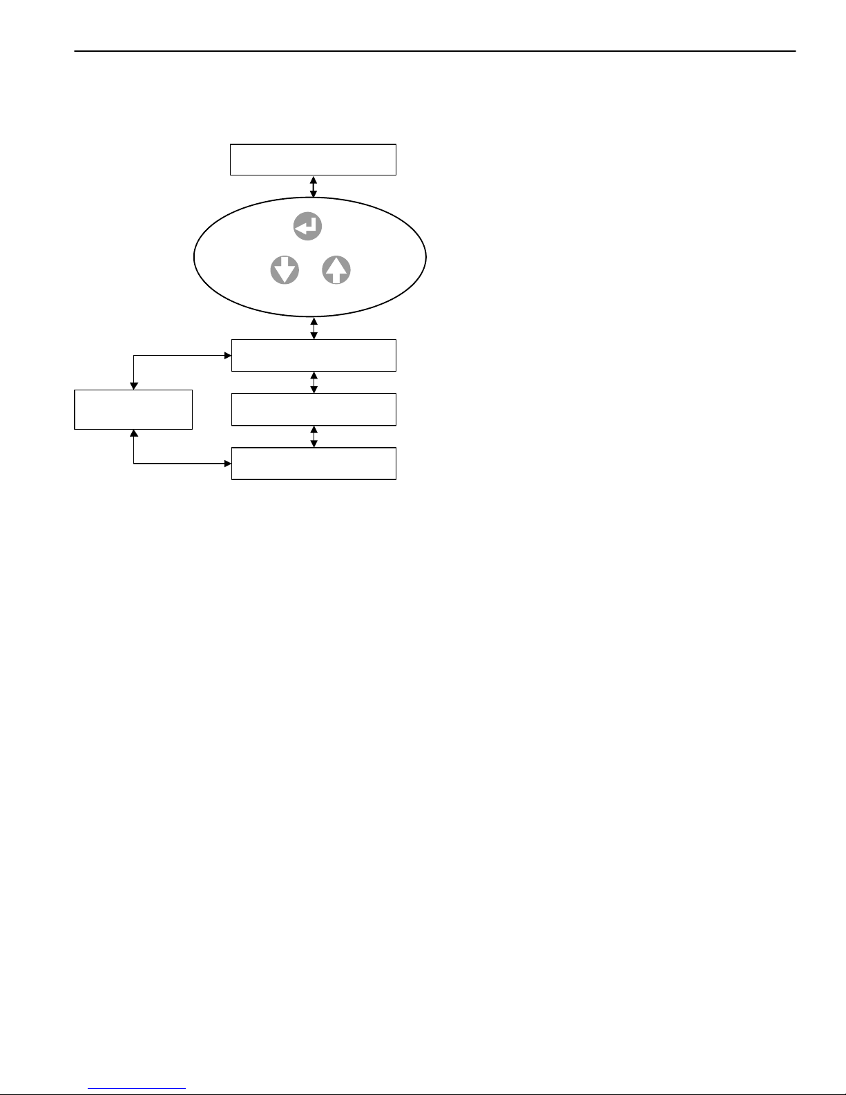
Operating controls and indicators 5...................................................................................................................................................................
Selection of operating level 6.................................................................................................................................................................................
Overview of control functions 7...........................................................................................................................................................................
Initial start-up/Configuration 25...............................................................................................................................................................................
Functions 28.........................................................................................................................................................................................................................
Operating status 29.........................................................................................................................................................................................................
Room setpoint temperature 32.................................................................................................................................................................................
Cascade Control heating curve 32.........................................................................................................................................................................
Multiple-boiler control unit 43...................................................................................................................................................................................
Heating system pump 44............................................................................................................................................................................................
Safety functions 45.........................................................................................................................................................................................................
Technical Specifications 48........................................................................................................................................................................................
Sensor resistance table 48..........................................................................................................................................................................................
Technical data 48............................................................................................................................................................................................................
Product information
Outdoor reset cascade control for multiple boiler installations with up to four gas-fired wall-mounted boilers and
one heating system pump.
Terminology
The terminology used by the cascade control may not always coincide with the terms used in the North
American market. The following is a cross-reference chart between the terms used by the control and
corresponding, more commonly used, terms of the North American heating industry.
Term used by control North American term
Flow Supply
Frost protection Freeze-up protection
Outside temperature Outdoor temperature
Desired Setpoint temperature
Time clock Timer
5285 565 v1.3

4
Safety
Important regulatory and installation requirements
The cascade control must only be used in conjunction with a CSA certified Vitocontrol-S or Vitocontrol-C boiler and system
control panel.
Power supply
Install power supply in accordance with
the regulations of the authorities hav-
ing jurisdiction or, in the absence of
such requirements, in accordance with
National Codes.
Note on connecting external “potential-
free” contacts to the cascade control
Ensure that all contacts have sufficient
insulation clearance to live parts and
are certified for these applications.
Working with an open control
No static discharge to the internal com-
ponentry must ever occur when work-
ing with opened control equipment.
About these instructions
Take note of all symbols and notations intended to draw attention to potential hazards or important product information.
These include ”WARNING”, ”CAUTION”, and ”IMPORTANT”. See below.
Warnings draw your attention to the
presence of potential hazards or
important product information.
Cautions draw your attention to the
presence of potential hazards or
important product information.
Helpful hints for installation,
operation or maintenance which per-
tain to the product.
This symbol indicates that additional,
pertinent information is to be found in
column three.
This symbol indicates that other
instructions must be referenced.
5285 565 v1.35285 565 v1.3
Indicates an imminently hazardous
situation which, if not avoided, could
result in death, serious injury or
substantial product/property damage.
WARNING
Indicates an imminently hazardous
situation which, if not avoided, may
result in minor injury or
product/property damage.
CAUTION
IMPORTANT

5
Operation
Operating controls and indicators
Display
Operating buttons
System diagram
Status indicators
Operating buttons
Use buttons , , and to display and/or change data in the main and/or sub-menus
(depending on configuration and operating level).
The function of each button is dependent on the menu item displayed when the button is pressed.
Function in normal mode:
Scroll up the menu and/or increase the nominal value.
Scroll down the menu and/or reduce the nominal value.
Back to the previous menu and/or reinstate the previous nominal value.
Menu selection and/or activation of the nominal value to change or confirm the nominal value.
Function during the configuration process (limited function):
Change the menu selection or increase the nominal value.
Change the menu selection or reduce the nominal value.
No function.
Confirm the nominal value and scroll to the next configuration menu item.
Status indicators
”9”:Hflashes if the control unit has been connected to the power supply but has not yet been
configured;
His lit (permanently) after configuration.
”1 to 4” and ” ”: is lit if the corresponding system component is operational.
”U”: is lit in case of faults.
5285 565 v1.3
4
3
2
1
1
2
3
4

6
Selection of operating level
The control unit has three operating levels:
Access level 1
Displays simple parameters, such as operating mode and software version.
Access level 2
Displays the most important operating details (e.g. actual and set supply temperatures, switching periods and
settings such as room temperature setpoint, supply temperature setpoint) and modification of nominal values.
Access level 3
System and device configuration.
Access to the operating levels
Press ; ”Function General” will be displayed.
When ”Function Cascade control” is displayed, select ”Function General” with and
confirm with .
Select ”Access level” with and confirm with ; access level 1, 2 or 3 will then be
displayed.
Press , figure ”1”or ”2” will then flash.
Enter the following access code for the required operating level:
for access level 2
for access level 3
Press , ”Access level” is then displayed.
This confirms the selection of the required operating level.
Press to return to ”Function General” in the access level that the code was
entered for.
Please note:
The control unit automatically reverts to Access level 1, if no button is pressed within an hour.
5285 565 v1.3
Function 001-A
General
Access level
Access level 1
[]
Access level
Function 001-A
General

7
5285 565 v1.3
Function 001-A
General
Date/Time
Access Level
Operation Data
Return to
Date/Time
Level 1
General function
View current date and time.
Access level to alternate menus.
Software type and version.
Use or to
select desired function
Press
5285 565 v1.3

8
Function 001-B
Cascade
Faults
Status
Fault
Flow (Temp)
Desired (Temp)
Level 1 Cascade Control
No adjustments
OR
When system
fault detected
Default display
no system faults
Operation Data
Time Clock
Holidayprogramme
Software Version
Time Clock
Normal Operation
Flow (Temp)
Desired (Temp)
Time Clock
Outside Temp (ºC)
Use or to
select desired function
Press
(no adjustment)
Program Timers
(no adjustment)
5285 565 v1.3

9
5285 565 v1.3
Function 001-A
General
Date/Time
Access Level
Operation Data
Return to
Date/Time
Level 2 General Function
Current date and time can be viewed and adjusted.
Access level to alternate menus.
View software type and version.
Use or to
select desired function
Press
5285 565 v1.3

10
5285 565 v1.3
Function 001-B
Cascade
Faults
Status
Fault
Flow (Temp)
Desired (Temp)
Level 2 Cascade Control
Adjustments
OR
When system
fault detected
Default display
no system faults
Operation Data
Time Clock
Holidayprogramme
Software Version
Time Clock
Normal operation
Flow (Temp)
Desired (Temp)
Outside Temp (ºC)
Nominal Values
Use or to
select desired function
Press
5285 565 v1.3
Autres manuels pour VITODENS 200
15
Table des matières
Autres manuels Viessmann Panneau de contrôle

Viessmann
Viessmann Vitotronic 200 GW1 Manuel utilisateur

Viessmann
Viessmann 5548 Manuel utilisateur

Viessmann
Viessmann Vitotronic 100 GC1 Mode d’emploi

Viessmann
Viessmann Vitocontrol-S, WB2 Dimensions et guide d'installation

Viessmann
Viessmann 5549 Manuel utilisateur

Viessmann
Viessmann 5545 Manuel utilisateur

Viessmann
Viessmann VITOTRONIC 100 Manuel utilisateur

Viessmann
Viessmann 5549 Manuel utilisateur

Viessmann
Viessmann 5545 Manuel utilisateur

Viessmann
Viessmann 5546 Manuel utilisateur


