Vestamatic Touch Centre XL 4C Wired Manuel utilisateur

Central controls for sunshade devices,
skylights, lighting, ventilation and heating
Installation and Operating Instructions

© Vestamatic GmbH Subject to modifications!
- 2 -
Art.
-Nr.: 84500601 K1• Vestamatic GmbH • Dohrweg 27 • D-41066 Mönchengladbach • www.vestamatic.com
Contents
Contents 2
-
4
Safety precautions / Explanation of warning signals 5
Delivery extent 6
Functional description 7
Technical data 7
Information for the installer 8
Control box 8
General notes 8
Housing installation 9
Wiring diagram 10
-
11
Power supply 12
Connecting 230VAC motors 13
Connecting decentralised controls 14
Assembly / Connection of wind sensors 15
-
16
Assembly / Connection of lux sensors 16
-
17
Assembly / Connection of rain sensors 18
-
19
Assembly / Connection of temperature sensors 20
-
21
Assembly / Connection of DCF radio-controlled clock receiver 21
-
22
Connection of buttons for external operation of channel groups 23
Connection the maintenance switch 24
Connecting the control system to a smoke/fire alarm system 25
Display box 26
Connecting the display box to the control box via 4-wire interface 26
-
27
Installation assistant (Wizard) 28
Quick reference guide 28
General notes 29
Password input 29
Wizard start 29
Setting the user interface language 29
Communication mode recognition 30
Scanning connected sensor devices 30
Selection of connected channel group 31
Selection of sensors from connected sensor devices 31
Lux sensor assignment 32
Wind sensor assignment / Wind sensor type setting 32
Temperature sensor assignment 33
Rain sensor assignment 33
Activating the device lock function 33
-
34
Wizard end 34

© Vestamatic GmbH Subject to modifications!
- 3 -
Art.
-Nr.: 84500601 K1• Vestamatic GmbH • Dohrweg 27 • D-41066 Mönchengladbach • www.vestamatic.com
Contents
Information for the user 35
General notes 35
-
36
Weather info / Display lock / Comfort program 36
-
37
Basic settings 38
Quick reference guide 38
Detail 1/3 39
Setting the time / date 39
Setting the display colour selection 40
Setting the display standby time 40
Release following fire alarm 40
Detail 2/3 41
Network settings (without function) 41
Display logbook 41
Display contact details 42
Display software version and serial number 42
Detail 3/3 42
Move to safety position 42
Touchscreen calibration 43
Display/Start wizard 43
Restore factory settings 44
Fine adjustments 45
Quick reference guide 45
Detail 1/5 46
Sun function 46
Setting extension sun threshold 46
Setting extension response time 47
Setting retract time delay 47
Setting retract sun threshold 47
Setting sun motor runtime 47
Setting number of sun-dependent extension commands per day 48
Rain function 48
Setting rain reset delay 48
Setting rain sensitivity setting 48
Setting manual extension when rain/frost 49
Wind function 49
Setting wind threshold 1 50
Setting wind threshold 2 50
Setting wind response delay 51
Setting wind reset delay 51
Setting wind unit 51
Temperature function 52
Setting temperature threshold 1 52
Setting temperature threshold 2 52
Setting motor run time for temperature threshold 2 53
Setting temperature reset delay 53
Setting temperature unit 53

© Vestamatic GmbH Subject to modifications!
- 4 -
Art.
-Nr.: 84500601 K1• Vestamatic GmbH • Dohrweg 27 • D-41066 Mönchengladbach • www.vestamatic.com
Contents
Detail 2/5 54
Motor run time 54
Tilting function 54
Selection of tilting type 55
Setting tilting time “season” 56
Setting tilting time “table” 56
Setting tilting assignment 56
Continuous up command / Continuous down command 57
Detail 3/5 58
MC DZ M/J function 58
Inching mode function 58
Holiday function 59
Astro function 59
Astro setting 59
Setting longitude LON 60
Setting latitude LAT 60
Setting up time correction 60
Setting down time correction 60
Detail 4/5 61
UP time function 61
DOWN time function 62
Automatic mode lock 62
Programming/deleting handheld transmitter (without function) 63
Detail 5/5 63
Heating function 63
Setting temperature threshold 64
Setting anti-freeze 64
Setting reset delay 64
Setting temperature unit 64
Ventilation function 65
Setting temperature threshold 65
Setting reset delay 65
Setting temperature unit 65
Control system warning signals 66
List of cities for the Astro function 67
Symbol description 68
-
72
Manufacturer’s default settings 73
-
75
Personal settings 76
-
78
Troubleshooting 79
-
81
Cleaning / Disposal of waste 82
Customer service 82

© Vestamatic GmbH Subject to modifications!
- 5 -
Art.
-Nr.: 84500601 K1• Vestamatic GmbH • Dohrweg 27 • D-41066 Mönchengladbach • www.vestamatic.com
Safety precautions / Explanation of warning signals
Ä
– Contact a professional electrician to install the control system, because the control
system requires a power supply of 230VAC, 50 Hz.
– Check the control system for signs of mechanical damage after unpacking. If you notice
any shipping damage, do not start up the control system and notify your supplier
immediately.
– The control should only be used for the purpose specified by the manufacturer (refer to
the operating instructions). Any changes or modifications thereof are not permissible
and will result in loss of all warranty claims.
– If it is no longer possible to guarantee the safe operation of the control or the connected
devices, you should turn the control off immediately and make sure that it cannot be
operated unintentionally.
– Before carrying out work on sunshading devices or skylights which are operated by the
control, you must switch off the control box power supply.
– For safety reasons, if there is no rain or frost sensor connected to the control you are
advised, depending on the sunshade design, to set the control to manual operation if the
temperature drops below +1
°C. This will prevent the sunshade from extending automati-
cally (e.g. due to the sun).
– This device contains a pollutant battery. The end user must recycle all used batteries in
accordance with regulation 91/157/EWG). Disposing of the batteries in household waste
is strictly forbidden.
– The use of a power pack other than the optional power pack supplied by the control’s
manufacturer may limit the functions available and/or damage the control. Such use is
therefore not permitted.
– In the event of a power failure, the control and all connected devices will no longer be
operable.
– For safety reasons, if a severe weather warning is issued, retract all connected devices
and change the operating mode of all groups to manual operation mode.
Ä
Danger
There is an imminent danger to the life and health of personnel. Any failure to follow the
hazard warnings will immediately put personnel at risk.
Ä
Warning
There is a potential danger to the life and health of personnel.
Ä
Caution
A situation which has an undesirable consequence. The extent of health damage is
small. Example: foreseeable operating errors.
Ä
Attention
Material damage to the device may result if the hazard warnings are not followed.
I
Failure to comply will result in product handling faults, but not in damage to property or
personal injury.
h Application advice and useful information on how to make best use of the product.

© Vestamatic GmbH Subject to modifications!
- 6 -
Art.
-Nr.: 84500601 K1• Vestamatic GmbH • Dohrweg 27 • D-41066 Mönchengladbach • www.vestamatic.com
Delivery extent
The following items are included:
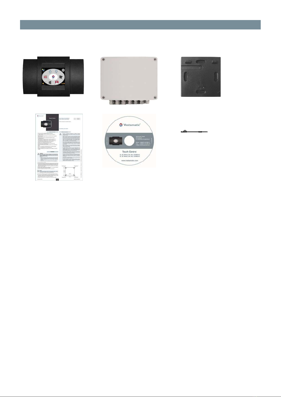
1ß
and
2ß
3ß
4ß
5ß
1ß Control device comprising display box and control box
2ß Wall mounting plate for display box
3ß Installation instructions
4ß Operating instructions on CD
5ß Stylus
Touch Centre versions:
Touch Centre XL 4C Wired Article-no.: 01080212
Touch Centre M 2C Wired Article-no.: 01080210
Accessories:
Lux sensor LS 30 Article-no.: 01161210
Wind sensor WS XS Article-no.: 01100310
Wind sensor WS XS Alu Article-no.: 01100410
Wind sensor WS Classic M Article-no.: 01100235
Power supply PS Classic M (for WS Classic M) Article-no.: 01100290
Rain sensor RD +1 °C Article-no.: 010830
Rain sensor RD -20 °C Article-no.: 010825
Temperature sensor TS Pro XL Article-no.: 01173010
Thermostat TE Indoor Article-no.: 01100271
Thermostat TE Outdoor Article-no.: 01100282
DCF Receiver Article-no.: 01306300

© Vestamatic GmbH Subject to modifications!
- 7 -
Art.
-Nr.: 84500601 K1• Vestamatic GmbH • Dohrweg 27 • D-41066 Mönchengladbach • www.vestamatic.com
Functional description
The Touch Centre is a microprocessor-controlled central control for different products such as blinds,
awnings, shutters, skylights, ventilation systems, heating and lighting. The control system is intended for use
in medium-sized projects with up to 4 façades and/or floors.
The connected sunshade and locking systems are centrally controlled according to sun intensity, wind
speed, precipitation and time. External systems, such as safety windows, fire alarms or building control
services systems, can be easily integrated.
The sensor inputs make it possible to connect simultaneously (depending on control system type) up to:
2 wind sensors (heated / not heated)
8 lux sensors
1 rain sensor
2 Temperature sensors
1 DCF 77 Receiver
Additional connections:
4 up/down group buttons
1 maintenance switch
1 connection for fire alarm centers
The display box controls and communicates via the in-built 4-wire RS485 interface. Operating and
setting the connected sunshade devices is simple thanks to the coloured touchscreen display in the
display box with its clear symbol options.
Power supply: 230VAC, 50 Hz
Impulse voltage withstand level: 2.5 kV
Rated power: 10 W
Max. load per output: 250VAC, 4A, cos f > 0.8 ind.
Max. rated power: 1380 W, 6A, 230VAC
Align switching time extend: 3 – 180 seconds or continuously
Software class: A
Conductor cross-section –
Motor connection:
Sensors/Button:
0.14 mm – 2.5 mm²
0.14 mm – 1.5 mm²
Operating temperature: 0°C (32°F) to +40°C (104°F)
IP class:
IP 20 (control box)
IP 20 (display box)
Degree of contamination:
2 (control box)
2 (display box)
Battery: CR 2032
Dimensions (L × W × H):
270 × 220 × 108 mm (control box)
155 × 105 × 35 mm (display box)
Colour information:
Display box: black (similar to RAL 9005) / standard version
Control box: light grey (similar to RAL 7035)
Conformity:
p
Technical data

© Vestamatic GmbH Subject to modifications!
- 8 -
Art.
-Nr.: 84500601 K1• Vestamatic GmbH • Dohrweg 27 • D-41066 Mönchengladbach • www.vestamatic.com
Information for the installer
–
Control box
General notes
Connecting skylight motors
Ä
ATTENTION!
When connecting skylights, the terminal UP corresponds to the close skylight
command, and the terminal DOWN corresponds to the open skylight command.
Connecting fan motors or heating/lighting fittings
Ä
ATTENTION!
– When connecting fan motors or heating/lighting fittings the terminal UP corre-
sponds to the command fan/heating/lighting ON.
– The terminal DOWN does not have a function in the case of fan motors or heating/
lighting fittings.
– Check the rated power of the connected devices. The total power consumption
of the connected devices must not exceed 1380 W. If the power consumption of
the connected devices exceeds 1380 W, the isolating relay MC TR 1 PF (01054720)
must be used for each channel group.

© Vestamatic GmbH Subject to modifications!
- 9 -
Art.
-Nr.: 84500601 K1• Vestamatic GmbH • Dohrweg 27 • D-41066 Mönchengladbach • www.vestamatic.com
Information for the installer
–
Control box
Housing installation
Ä
WARNING!
Risk of injury due to improper installation and commissioning.
Improper installation and commissioning may lead to personal injury or property
damage.
Therefore:
– When connecting the device, observe the currently valid VDE standards (in particular
DIN VDE 0100/0700), your local power company’s regulations and the current
accident prevention regulations.
– Connect the control in accordance with the wiring diagram.
1. Switch off the power supply
2. Unscrew the housing cover, take off the housing cover of the control box and mount the housing at
the outer four drill holes in the corners. The housing must be mounted such that the cable glands are
located underneath. The control box must be mounted in a position that is well protected from direct
sunlight.
3. Feed the cables through the cable inlets in the housing and tighten the inlet. Unused cable inlets must
be sealed.
4. Connect the cables in accordance with the wiring diagram.
I
NOTE!
Mount the control device so that it is inaccessible to adults, children and animals. All
cables must be permanently wired.
5. The output is floating (important for operating decentralised controls).
6. If one or more motors (230VAC, 50 Hz) resp. isolating relays are directly connected, a wire bridge
must be fitted between terminal Common of the motor output and terminal L of the mains connection.
7. Replace the housing cover and tighten the housing cover screws.

© Vestamatic GmbH Subject to modifications!
- 10 -
Art.
-Nr.: 84500601 K1• Vestamatic GmbH • Dohrweg 27 • D-41066 Mönchengladbach • www.vestamatic.com
Information for the installer
–
Control box
Wiring diagram
Autres manuels pour Touch Centre XL 4C Wired
1
Ce manuel convient aux modèles suivants
3
Table des matières
Autres manuels Vestamatic Contrôleurs

Vestamatic
Vestamatic MC P4 LoVo Manuel utilisateur

Vestamatic
Vestamatic MC P4 LoVo Manuel utilisateur

Vestamatic
Vestamatic IF SMI KNX 230VAC 16 Manuel utilisateur

Vestamatic
Vestamatic Quattro Lite Manuel utilisateur

Vestamatic
Vestamatic DZ-Plus R Manuel utilisateur

Vestamatic
Vestamatic Rolltec Pico Manuel utilisateur