Vescent Photonics D2-105 Manuel utilisateur

Laser Controller
Vescent Photonics, Inc.
www.vescentphotonics.com
4865 E. 41st Ave
Denver, CO 80216
Phone (303)-296-6766
Fax (303)-296-6783


General Warnings and Cautions
The following general warnings and cautions are applicable to this instrument.
WARNING
This instrument is intended for use by qualified personnel who
recognize shock hazards or laser hazards and are familiar with
safety precautions required to avoid possible injury. Read the
instruction manual thoroughly before using to become familiar
with the instrument’s operations and capabilities.
CAUTION
There are no serviceable parts inside the instrument. Work
performed by persons not authorized by escent Photonics may
void the warranty.
CAUTION
Although ESD protection is designed into the instrument,
operation in a static-fee work area is recommended.
WARNING
To avoid electrical shock hazard, connect the instrument to
properly earth-grounded, 3-prong receptacles only. Failure to
observe this precaution can result in severe injury or death.
WARNING
Do not clean outside surfaces of any escent Photonics products
with solvents such as acetone. Front panels on electronics
modules may be cleaned with a mild soap and water solution.
Do not clean optics modules.


Limited Warranty
escent Photonics warrants this product to be free from defects in materials and workmanship for a period of one year
from the date of shipment. If this product proves defective during the applicable warranty period, escent Photonics, at
its option, either will repair the defective product without charge or will provide a replacement in exchange for the
defective product. The customer must notify escent of the defective product within the warranty period and prior to
product return. The customer will be responsible for packaging and shipping the defective product back to escent
Photonics, with shipping charges prepaid.
escent Photonics shall not be obligated to furnish service under this warranty from damage caused by service or repair
attempts made without authorization by escent Photonics; from damage caused by operation of equipment outside of
its specified range as stated in either the product specification or operators manual; from damage due to improper
connection to other equipment or power supplies.
This warranty is in lieu of all other warranties including any implied warranty concerning the suitability or fitness of
the product for a particular use. escent Photonics shall only be liable for cost of repairs or replacement of the
defective product within the warranty period. escent Photonics shall not be liable for any damages to persons or
property resulting from the use of the product or caused by the defect or failure of this product. escent Photonics'
liability is expressly limited to the warranty set out above. By accepting delivery of this product, the purchaser
expressly agrees to the terms of this limited warranty.
escent Photonics
Printed Feb 22, 2012

Absolute Maximum Ratings
Note: All modules designed to be operated in laboratory environment
Parameter Rating
Environmental Temperature >15°C and <30°C
Environmental Humidity <60%
Environmental Dew Point <15°C

Vescent Photonics D2 Series Product Manual
1. Laser Controller
Model No. D2-105 / D2-105-500
Document Revision: 4
1.1. Description
The laser controller has two temperature controllers capable of sub-mK stability1 and a 200 mA or 500
mA precision current source based on the Libbrecht-Hall2 circuit. The laser controller is designed for
very fast current modulation via the servo input enabling high-speed servo control of the laser’s
frequency. The current servo input can accommodate input frequencies over 10 MHz and is limited by
the 1 kΩ input impedance. Additionally, an RF port is available for higher frequency modulation.
1 Sub-mK stability requires a proper thermal design and proper tuning of the temperature controller to the thermal
plant. If you did not purchase the Laser Controller with a Laser Diode, please read the section on tuning the
temperature controller.
2 Libbrecht and Hall, A Low-Noise, High-Speed Current Controller, Rev. Sci. Inst. 64, pp. 2133-2135 (1993).
7

Vescent Photonics D2 Series Product Manual
1.2. Specifications3
D2-1 5 D2-1 5-5 Units
Current Source
Current range 0-200 0-500 mA
Current noise density <100 <200
pA/
Hz
RMS Noise (10Hz - 100kHz) <50 <100 nA
RMS Noise (10Hz - 1MHz) <100 <150 nA
RMS Noise (10Hz - 10MHz) <300 <500 nA
Monitor Resolution (Display) 0.1 1 mA
Absolute accuracy 2 2 %
Temperature coefficient <1 <5 µA/°C
Current Servo Input
Input impedance 1000 1000 Ω
Bandwidth >10 >10 MHz
Modulation coefficient 1 1 mA/
RF Input Bandwidth 0.5 - TBD 0.5 - TBD MHz
Temp Servo Input
Input impedance 100 100 kΩ
Temp modulation coefficient
Gain = Low -20 -20 mK/
Gain = High -600 -600 mK/
Temperature Control
Temperature setpoint range 1-50 1-50 °C
Temperature isolation (T2)4TBD TBD mK/°C
Long term stability (T2) ~1 ~1 mK/day
Temperature coefficient 5
(controller, T2)
TBD TBD mK/°C
Max TEC current (voltage) 1 (4) 1 (4) A ( )
3All current noise measurements made with Laser Controller powered by D2-005 placed 5ft away from Laser Controller. Placing
D2-005 closer to Laser Controller may increase 60 Hz noise and their harmonics. Specifications not guaranteed when Laser
Controller is powered by device other than D2-005, or when placed near power supply or other noise source..
4Laser module temperature changed while Laser Controller module held fixed.
5Laser module temperature fixed while Laser Controller temperature change.
8

Vescent Photonics D2 Series Product Manual
1.3. Inputs, Outputs, and Controls
Front Back
1.3.1. Monitor Section
The monitor section contains a 3 ½ digit display and an output BNC for monitoring by an oscilloscope or
voltmeter. A selector knob controls which of six signals are relayed to the display and BNC. An LED
indicator is below the display to show which signal is being displayed and its units.
9
Vescent Photonics, Inc.
Denver, Colorado USA
MADE IN U.S.A.
Power I/O Power I/O
Remote Interlock
Setpo nt
Input
Setpo nt
Enable
Short
Open
= On
= Off
Model: D2-105
Laser
Enable
T1
set
I I
l m
∆
T1 T2
set
∆
T2
mA mA C mK C mK
T1 = Hous ng Temp
T2 = Laser Temp
∆
= Temp Error
Mon tor
Laser Controller
DIM
Temp Control
T2 Set
T2
T1
Power
Servo
Standby
Temp
Status
Laser
On
on
off/reset
Current Control
RF
Input
Current
Servo
Input
Coarse
Current
Laser
Laser
Current
Output
Current
L m t
Set
Temp
Lock
Temp
Servo
Input
Laser
Temp
Output
F ne
Current
Current
L m t
Mon tor
Output
199.9
Vescent Photonics, Inc.
Denver, Colorado USA
MADE IN U.S.A.
Power I/O Power I/O
Remote Interlock
Setpo nt
Input
Setpo nt
Enable
Short
Open
= On
= Off
Model: D2-105
Laser
Enable
T1
set
I I
l m
∆
T1 T2
set
∆
T2
mA mA C mK C mK
T1 = Hous ng Temp
T2 = Laser Temp
∆
= Temp Error
Mon tor
Laser Controller
DIM
Temp Control
T2 Set
T2
T1
Power
Servo
Standby
Temp
Status
Laser
On
on
off/reset
Current Control
RF
Input
Current
Servo
Input
Coarse
Current
Laser
Laser
Current
Output
Current
L m t
Set
Temp
Lock
Temp
Servo
Input
Laser
Temp
Output
F ne
Current
Current
L m t
Mon tor
Output
199.9

Vescent Photonics D2 Series Product Manual
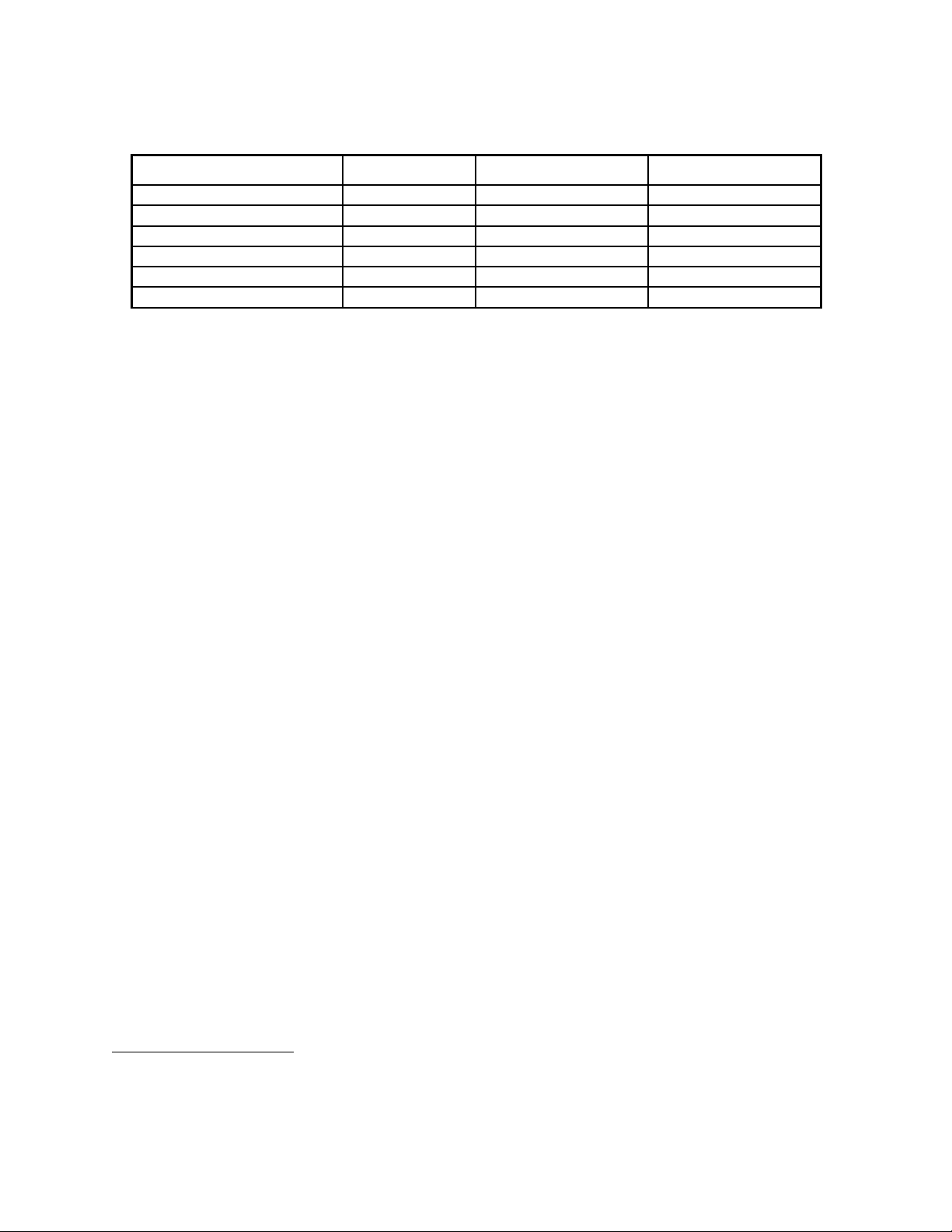
Name Symbol Units Resolution
Current I mA 0.1 mA / 1mA6
Current limit Ilim mA 0.1 mA / 1mA6
Housing Temperature Set T1set °C 0.1 °C
Housing Temperature Error ∆T1 mK 0.1 mK
Laser Temperature Set T2set °C 0.1 °C
Laser Temperature Error ∆T2 mK 0.1 mK
NOTE When the Laser Switch is in the “Off / Reset” position, the laser diode is shorted to ground and
no current is flowing through the laser diode. However, the Current Monitor will read up to 30 mA of
current flowing through the short. This is normal. When the switch is in the “ON” position, the current
monitor accurately measures the current flowing through the laser diode.
1.3.2. Current Control
Current Lim (LED)
The current limit indicator lights when the current limit circuit is activated. If the user attempts to
set the current over the current limit setpoint the circuit shunts the excess current through a
transistor to ground
Fine Current (knob)
The fine current adjusts the diode injection current by ½-1 % of the course control setting. Use
this control for fine positioning of the laser frequency prior to locking.
Course Current (Scale Dial)
The course current control sets the laser diode injection current between 0 and 200 mA (0 and
500mA for 500mA version). To set the current, switch the selector knob in the monitor section
so that the current LED (I) is lit. Then adjust the course current to the desired setting.
Current Limit Set (Trimpot)
The current limit set is a front panel trimpot adjustment. Set the selector knob to the Ilim position
and adjust the trimpot to the desired value. The Current Limit should be set below the maximum
current for the laser diode.
RF Input (BNC)
The RF input is ac coupled to the laser diode through a 10 nF capacitor. Over ~3 MHz the
impedance of this input will approach the ac impedance of the laser diode of ~5Ω. This input is
normally connected to the RF output from the Laser Servo module, which applies FM sidebands
at 4 MHz to the laser output.
Note a large voltage transient to this input could possibly cause damage to the laser diode. If
you are connecting other equipment to this input do not exceed 0.25 Vrms from a 50 Ω source or
1 mW of power.
Current Servo Input (BNC)
The current servo input adds or subtracts current though 1 k Ω connected to the laser diode giving
a modulation coefficient of 1 mA/ . A bias circuit sets the voltage of the current servo input to
6 1mA resolution with D2-105-500
10
Ce manuel convient aux modèles suivants
1
Table des matières
Autres manuels Vescent Photonics Contrôleurs


