Verkada BC82 Manuel utilisateur


Document
Document Details
Verkada Inc. 406 E 3rd Ave, San Mateo, CA 94401
All specifications are subject to change without notice
Copyright © 2023 Verkada Inc. All rights reserved.
V1.1 (20230606)
(V1.0 first published 20230315)
Firmware
Firmware version can be verified on
Verkada Command command.verkada.com.
Product Model
This install guide pertains to model BC82-HW.
2

Introduction
What’s in the box
What you’ll need
●A working internet connection
●A smartphone or laptop
●A #2 Phillips screwdriver or
power drill with a #2 Phillips driver bit
●3/16 inch (4.76 mm) drill bit for wall anchors
●A shielded Cat5 or Cat6 Ethernet cable
Verkada Inc. 406 E 3rd Ave, San Mateo, CA 94401
All specifications are subject to change without notice
Copyright © 2023 Verkada Inc. All rights reserved.
BC82 Alarm Console
3
Mount Plate
(Attached to Alarm Console)
Connect
For easy registration and setup, scan
the QR code on the back of the
product.
If you prefer to manually register your
product, please proceed to:
verkada.com/start
T10 Security Torx Screwdriver
Mount Template
(Attached to Alarm Console)
4 M4 x 25mm PH2 Wall Screws 4 Wall Anchors

Introduction
Overview 1/2
Verkada Inc. 406 E 3rd Ave, San Mateo, CA 94401
All specifications are subject to change without notice
Copyright © 2023 Verkada Inc. All rights reserved.
4
LED Behavior
Solid Orange
Console is on and booting up.
Flashing Orange
Console is updating firmware.
Status LED
Speaker & Buzzer
10.1” Touchscreen
Flashing Blue
Console can receive events but
cannot reach the server.
Solid Blue
Console is running, connected, and
receiving events.
Camera
Microphone

Introduction
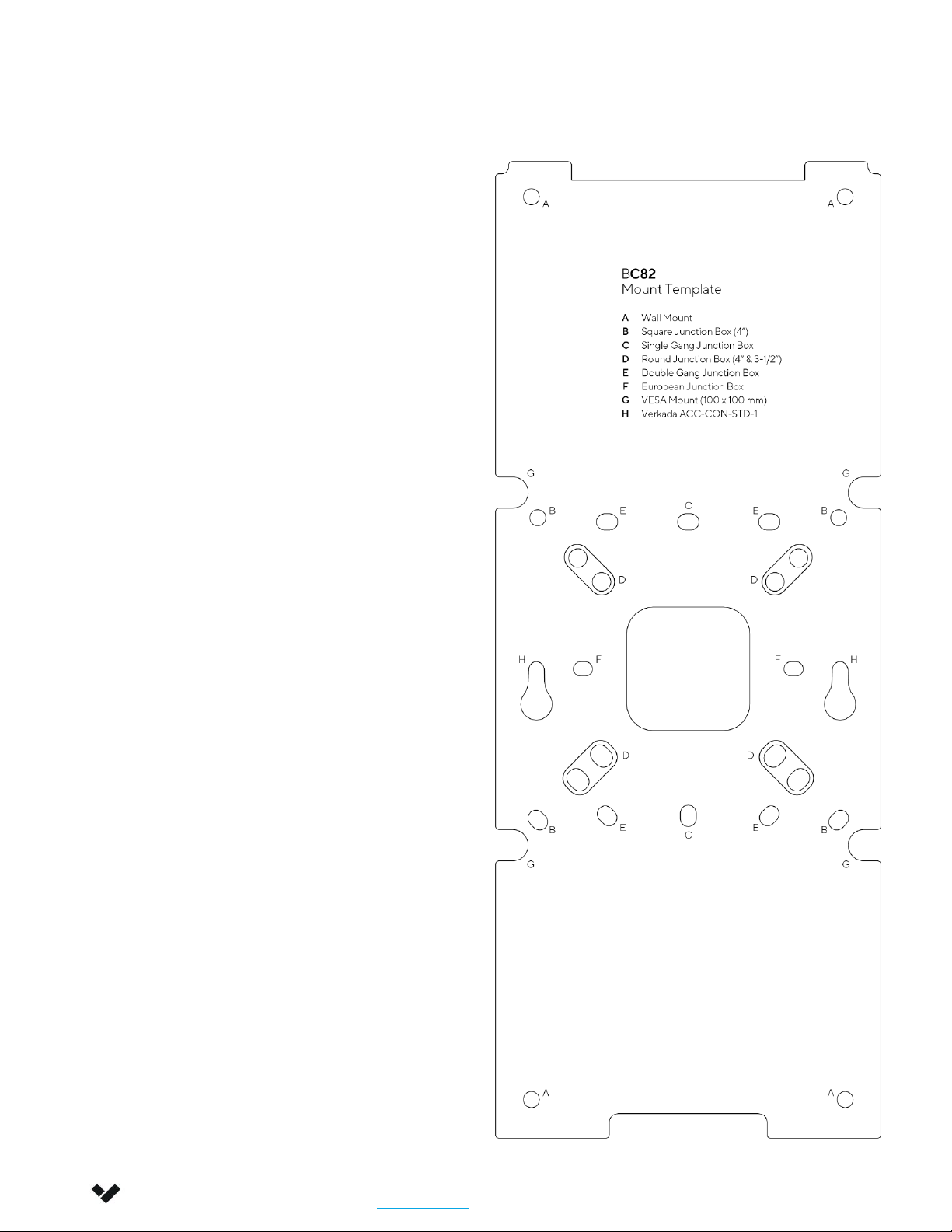
Mount Template
Verkada Inc. 406 E 3rd Ave, San Mateo, CA 94401
All specifications are subject to change without notice
Copyright © 2023 Verkada Inc. All rights reserved.
6
A
B
C
D
E
F
G
H
Wall mount
Square Junction Box (4”)
Single Gang Junction Box
Round Junction Box (4” & 3-½”)
Double Gang Junction Box
European Junction Box
VESA Mount (100x100 mm)
Verkada ACC-CON-STD-1
Use the mount template to mark the
appropriate hole pattern.

Verkada Inc. 405 E 4th Ave, San Mateo, CA 94401
All specifications are subject to change without notice
Copyright © 2022 Verkada Inc. All rights reserved.
Introduction
Technical Specifications
Power Consumption 25W
Battery Life 10-hour battery backup (34.4 watt-hour rechargeable lithium-ion battery)
Power Input
Parameters
DC 10V-36V VDC input; 2.8A-1.29A
PoE42V-57V VDC input; 0.60A-0.44A
Connectivity
Ethernet 10/100Mbps
Bluetooth 5.0
Dual Band (2.4GHz/5GHz) WiFi, 802.11 ac/abgn
Sub-GHz transceiver (863MHz - 928MHz)
2x USB 2.0, 1x RS485
Display 10.1” LED-backlit multi-touch, 1960 x 1200 resolution
Processor Quad-core ARM Cortex-A53 64-bit processor
Camera 8MP Camera, 1080p HD video
Audio
Mono speaker (88 dB at 1 meter)
Buzzer (85dB at 3 meter)
3.5mm jack for external self-powered speakers
Dual microphones
Dimensions Tablet: Height: 309.9mm / 12.2 in; Width: 161.3mm / 6.4 in; Depth: 40.3mm / 1.6 in
Mount: Length: 281.9mm / 11.1 in; Width: 113.9mm / 4.5 in; Height: 17.5mm / 0.7 in
Operating
Temperature 0°C to 40°C / 32°F to 104°F, 5-90% humidity
Weight Tablet: 1,240 grams / 2.7 lbs
Mount: 400 grams / 0.9 lbs
Included Accessories T10 screwdriver, x4 wall screws,
x4 drywall anchors
Mounting Options Wall Mount Bracket
7

Installation
Connect and register
Verkada Inc. 406 E 3rd Ave, San Mateo, CA 94401
All specifications are subject to change without notice
Copyright © 2023 Verkada Inc. All rights reserved.
8
Use the provided T10 Security Torx
screwdriver to loosen the security screw.
Slide the mount plate downwards to
remove it.
Connect the Ethernet cable to the
PoE.af/.at port on the back of the
Console..
Press the power button once and wait
for the Status LED and screen to turn on.
Please note: Bootup sequence may take
several seconds.
For easy registration and setup, scan
the QR code on the product.
If you prefer to manually register your
product, refer to the serial number on
screen and proceed to:
verkada.com/start

Installation
Mounting 1/2
Verkada Inc. 406 E 3rd Ave, San Mateo, CA 94401
All specifications are subject to change without notice
Copyright © 2023 Verkada Inc. All rights reserved.
9
Please note: Avoid mounting the Console in
direct sunlight for optimal device performance.
Use the mount template to mark the appropriate
hole pattern on the mounting surface.
Use the wall anchors and screws to attach the
mount plate onto the desired surface.
A
B
C
D
E
F
G
H
Wall mount
Square Junction Box (4”)
Single Gang Junction Box
Round Junction Box (4” & 3-½”)
Double Gang Junction Box
European Junction Box
VESA Mount (100x100 mm)
Verkada ACC-CON-STD-1
Use the mount template to mark the
correct hole pattern.
Cables can be routed through the
surface, or along the surface.
Option 1
Cable routing through
the surface
Option 2
Cable routing
along the surface

Installation
Mounting 2/2
Verkada Inc. 406 E 3rd Ave, San Mateo, CA 94401
All specifications are subject to change without notice
Copyright © 2023 Verkada Inc. All rights reserved.
10
Connect the Ethernet cable, and any
other cables relevant to your installation,
to the Alarm Console.
Press the power button once and wait
for the Status LED to turn on.
Please note: Bootup sequence may take
several seconds.
Engage the three hook features on the
mount plate and slide the console
down.
To secure, tighten the captive security
screw, using the provided T10 Security
Torx screwdriver.
Autres manuels pour BC82
1
Table des matières


