Verizon CR338 Manuel utilisateur

Customer Care:
(877) 477-4874www.vanguardprotexglobal.com/verizon-directory
For ALL videos and guides, visit our directory:
QUICK START GUIDE
FREESTANDING HOME SERVICES
WALL MOUNTED HOME SERVICES

TABLE OF CONTENTS
Smart Freestanding Home Services
Smart Wall Mounted Home Services
EnCore Installation
CR338 Installation
Slim Wearable Sensor Installation
Accessory Security
Adhesive Resistant Devices
CR338 Removal
IR Keyfob Troubleshooting
Spare Parts
1-2
3
4
5-6
7
8
9
10
11

1
Rev.09/01/2021
SMART
EnCore | CR338 | Slim Wearable Sensor
FREESTANDING HOME SERVICES
WALL MOUNTED HOME SERVICES
CORRECT
INCORRECT
Back to Table of Contents
VP-1397W K-CR338-02W VZW-Wearable3
INSTALLATION IS THE SAME FOR BOTH FIXTURES
The EnCore can be placed in the
bottom of the xture behind the
removable panel on the side wall.
CR338 positions will adhere
to the top of the Smart
Freestanding or Smart Wall
Mounted Home Services shelf.
CR338 - Phone & Tablet Security EnCore - Accessory Security
CR338
Bottom View
EnCore
Bottom View
Ensure the tamper switch is
depressed prior to securing
the EnCore in place.
How to Remove Front Panel
Lift, then pull the front panel to
remove from the xture.
Ensure the tamper switch is depressed
and the power cord is properly aligned
prior to securing the pedestal in place.
CR338
Side View
2
Rev.09/01/2021
SMART
EnCore | CR338 | Slim Wearable Sensor
FREESTANDING HOME SERVICES
WALL MOUNTED HOME SERVICES
X-Sensor
VP-1350WXL
Type-C
VP-1439W
Micro USB
VP-1349WXL
Back to Table of Contents
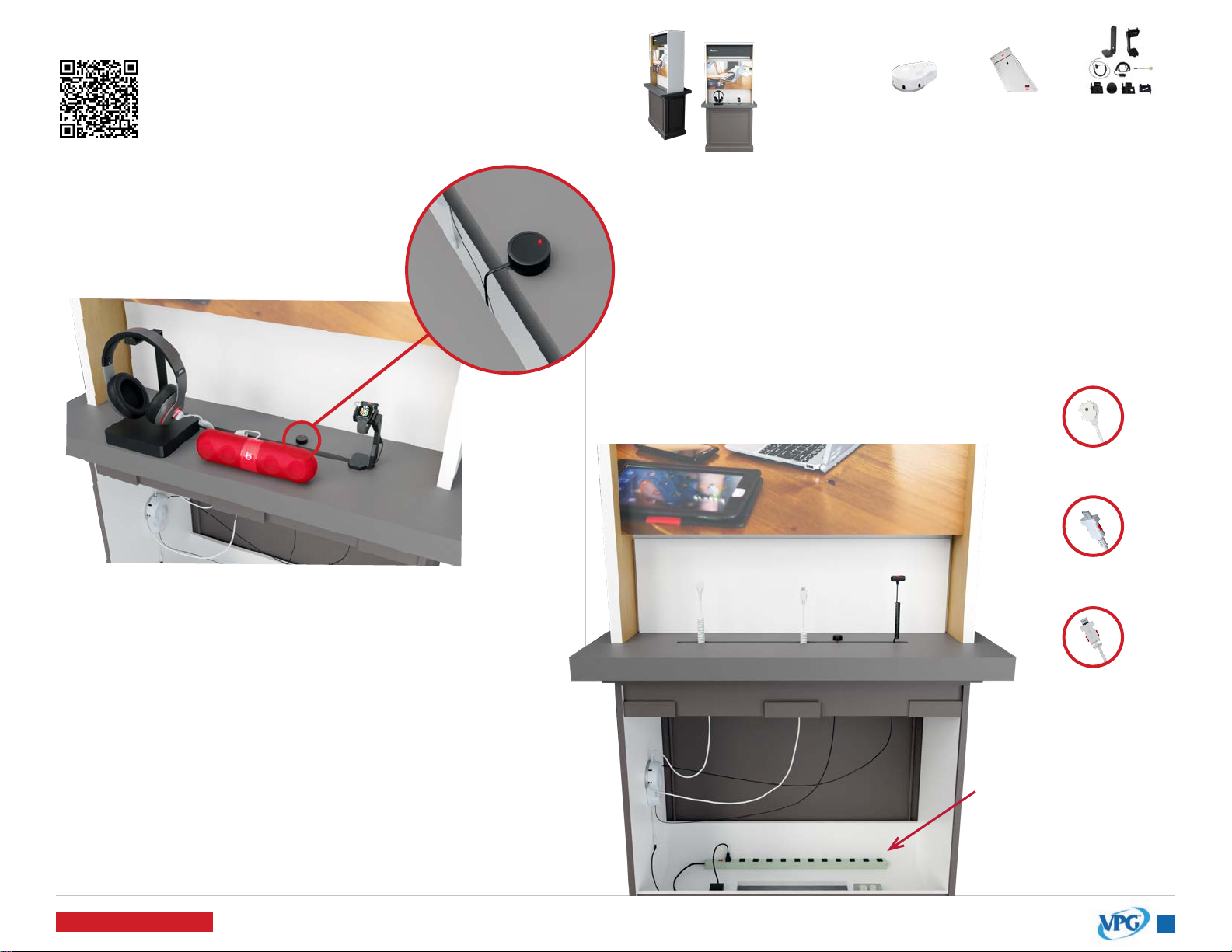
Sensors can route behind the shelf, and up through the slot.
Micro-USB, Type-C, and X-Sensors feed up through the xture and
plug in, or adhere to products.
Up to 5 sensors are used with the EnCore. Typically, you will not
use all 5.
The power cable can
be routed behind the
shelf and plugged
into the power supply
behind the panel at
the bottom of the
xture.
VP-1397W K-CR338-02W VZW-Wearable3
INSTALLATION IS THE SAME FOR BOTH FIXTURES
The IR extender cable is used to extend the EnCore receiver.
Feed the cable up through the xture slot and adhere the
dome to the top shelf close to the edge of the slot.
When it’s plugged in, you will see a green light illuminated
on the dome.
To arm and disarm the EnCore alarm, point the IR keyfob at
the dome.
Sensors - Accessory SecurityIR Extender Cable (KF-1102)
Accessory Security
Power Supply
IR Extender
KF-1102
3
Rev.09/01/2021
ENCORE
Installation click or scan QR code
for installation video
Back to Table of Contents
123
5 64
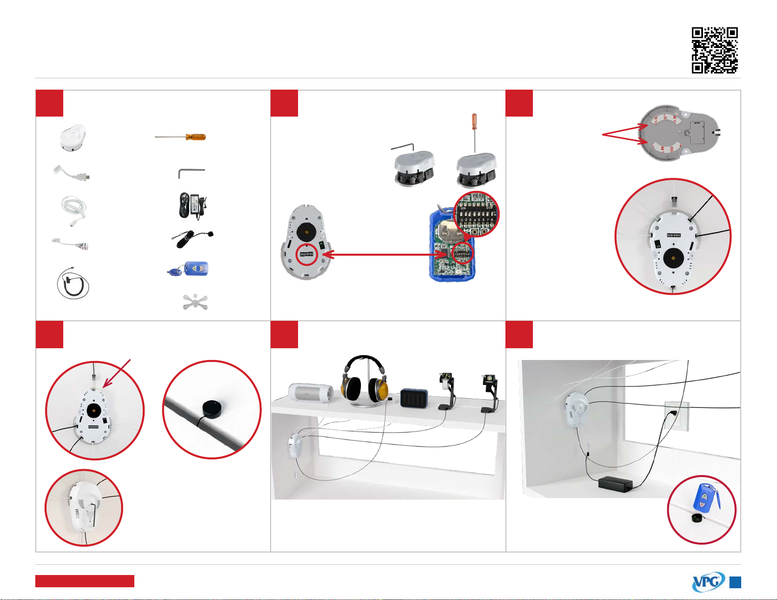
IMPORTANT: The code must match the
switches inside the IR Keyfob.
Remove the cover of the EnCore
(VP-1397) with the V-T900 security
driver or V-900-T Allen wrench.
Set the security
code by changing
the DIP switch
inside the EnCore. Clean the xture
surface. Then,
adhere the EnCore
to the xture. Hold
in place for 30
seconds.
Plug the
appropriate VPG
accessory sensors
into the Encore.
Remove the 3M
adhesive liner.
V-T900
V-900-T
KF-1102
V-37
KF-1106
VP-1397W
VP-1439W
VP-1349WXL
VP-1350WXL
or
or
or
Switch #8 changes
the sensor LEDs to red.
Reinstall the EnCore cover.
Plug the IR Receiver cable into the
back port of the EnCore.
Thread the sensor cables through the
xture. Install the sensors to the products.
Point the IR Keyfob at the IR
Reciever and press the red
lock button to arm the EnCore
Plug the V-37 power supply into the
EnCore’s power connector
Tools & Parts Needed
VP-1524C
VP-1626
or
or
Adhere the IR dome close
to the edge of the xture
slot. The IR Receiver will
accept the keyfob’s IR
signal for the EnCore.

4
Rev.09/01/2021
CR338
Installation
123
6 75
4
8
click or scan QR code
for installation video
Back to Table of Contents
Tools & Parts Needed
Arm the system
by pressing the
red “lock” button
on the IR Keyfob
(KF-1106). Point
the keyfob near
the black receiver
above the LED.
Plug the power
supply into the
pedestal and
into an AC
outlet.
Make sure the tamper switch
is fully depressed and properly
aligned before mounting.
CORRECTINCORRECT
Side View
Clean xture surface and wipe dry.
Remove the adhesive liner on the
base of the pedestal and adhere
the pedestal to the xture.
IMPORTANT: Hold for 30 seconds to
ensure a strong bond.
Bottom View
System is on battery only if LED is
ashing quickly. Must have power
plugged in to arm the system.
Tamper Switch
ADHESIVE MOUNTING
(for xtures WITHOUT overlay) ADAPTER MOUNTING
(for xtures WITH overlay)
Adhesive Tape
Adhesive Liner
ADAPTER MOUNTING
(for xtures WITH overlay)
A. Thread the pedestal power cord
through the adapter and screw to
the bottom
of the pedestal.
B. Place
connected
pedestal and
adapter through the hole in the
xture and tighten nut.
VP-1751W AD-238-8
oror
KF-1106
AD-239-5
AP-001-200
VP-1707W
V-39
P-21012 P-21006 P-21002
*K-1140
*Single Hole Adapter may come installed
on pedestal.
IMPORTANT: This step & step 5A are
necessary if the single hole adapter
is NOT already installed on the
CR338 pedestal.
Fully remove both the adhesive liner
and the tape from the bottom of
the pedestal.
Plug the power
coupler into sensor
and device.
*if coupler is not plugged
in, system will not alarm.
Remove adhesive
liner on sensor and
adhere to the center
of the device.
Clean the back of the
device with an alcohol pad
and wipe dry.
Attach the sensor to the
pedestal by twisting the boot
into the sensor.
IMPORTANT: If you are securing a
glass back device, see page 8 prior
to adhering sensor.

5
Rev.09/01/2021
SLIM WEARABLE SENSOR
Installation
1 2
3 4
click or scan QR code
for installation video
Back to Table of Contents
Tools & Parts Needed
VP-1626
V-T900
VP-1625
Generic
V-37
VP-1636
VP-1559
Apple
VP-1397W
or
VP-1433M
VP-1635
Samsung
VP-1656
Garmin
VP-1657
Generic
VP-1664
Galaxy Active
VP-1694
Gizmo
VP-1689
Mont Blanc
or
or
or
or
or
Cradles
Stands
Alarms
Thread the watch charger through the stand as shown.
Insert the watch stand into the bottom of the black Wearable
Riser box. Thread the watch sensor cable through the watch
stand and riser as shown.
Install the Wearable Riser’s base plate with the 4 Phillips head screws.
V-T99
Bottom View
Bottom View
Side View

6
Rev.09/01/2021
SLIM WEARABLE SENSOR
Installation
5 6 7
8 9 10
click or scan QR code
for installation video
Back to Table of Contents
Close the Slim Wearable
Sensor onto the top watch
band and tighten with the
security driver.
Remove adhesive liner
and adhere the Flex
Sensor to the back of
the watch head.
Ensure the Flex Sensor will
not be crimped when the
watch is placed on the
display stand or xture.
Rest the watch on the stand,
and plug the sensor into the
EnCore alarm unit (VP-1397).
IMPORTANT: If the Flex Sensor is damaged
or missing, do NOT plug sensor into EnCore.
For the Apple Watch Cradle,
remove the rubber padding if using
a 42mm Apple Watch or larger.
Apply the circular adhesive to the back of
the watch puck. Thread the watch charging
cable through the watch cradle for the
specied device. Remove adhesive liner and
adhere the charging puck inside the cradle.
Use the appropriate watch cradle for
the product you wish to secure.
Screw the watch cradle to the watch stand
with the security driver
(V-T900).
Insert the provided binding screw into
the watch cradle.
Insert the Flex Sensor
(VP-1636) into the
sensor.
Loosen the screw
on the top of the
Slim Wearable
Sensor (VP-1626)
and remove the
clear shunt plug
on the side of the
sensor.

7
Rev.09/01/2021
DEVICES WITH INDUCTIVE CHARGING/CAMERAS
Accessory Security
Back to Table of Contents
X-Sensors
X-Sensors will be used on phones that use inductive
charging. No ex cover is necessary.
If the phone has a removable back, detachable
parts or pieces, or the battery can be removed, you
will need to use a secondary X-Sensor to fully secure it.
Thread the X-Sensor up through the slot in the table,
and adhere it near the top of the phone, clearing the
camera and other important features of the device.
Speakers & Other Devices w/EnCore
Speakers use a Type-C input for powering the device.
Use a VPG power and security Type-C sensor
plugged into the side of the device as shown.
The EnCore lights on the sensor will light up a steady
red when the product is secure.
Type-C Power & Security Sensors
Type-C PAS sensors are able to charge and secure
devices at the same time.
When applicable, use the retainer bracket that
comes with the sensor. These sensors work with the
EnCore, but remember, the EnCore is not designed
to charge phones.
Charge pads, speakers, and other small accessories
are perfect for the Type-C PAS plugged into an
EnCore alarm.

8
Rev.09/01/2021
ADHESIVE RESISTANT DEVICES
Merchandising Requirements | All Glass Back Phones
Back to Table of Contents
AD-218 - Clear Adhesive
Any device that has a glass back requires the AD-218 to
make sure VPG sensors properly adhere to the product.
1) Clean the back of the device with an alcohol pad
and wipe dry immediately.
2) Remove the adhesive liner from the AD-218.
3) Adhere the AD-218 to the back of the device.
4) IMPORTANT: Ensure the tamper switch on the CR338
sensor aligns with one of the 3 holes on the AD-218
adhesives.
Note: Heat (whether it be ambient or from the device)
plays a major role in the effectiveness of adhesives. For
optimal adhesive bond, phones should be displayed in a
cool, dry area.
Autres manuels Verizon Système de sécurité

Manuels Système de sécurité populaires d'autres marques


EDM
EDM Solution 6+6 Wireless-AE Manuel utilisateur

Highway Safety Group
Highway Safety Group EA401 Manuel utilisateur

Siren
Siren LED GSM Manuel utilisateur

Detection Systems
Detection Systems 7090i Instructions de montage

Se-Kure Controls
Se-Kure Controls MicroMini SK-4841 Manuel utilisateur

Siemens
Siemens FDM273 Manuel utilisateur