
Verizon Networkfleet 5500 Manuel utilisateur
1
Verizon Networkfleet
5000 PRODUCT LINE
INSTALLATION GUIDE
5500 Diagnostic Hardware (Light/Medium/Heavy Duty) | 5200
Non-Diagnostic Hardware (Universal)
Installation Guide

2
Table of Contents
Getting Started
Registration Form........................................................................................................................... 3
5000 Product Line
Unit Overview .................................................................................................................................. 4
Harness Options ............................................................................................................................. 5
Light/Medium Duty OBD-II Harness Installation........................................................................... 7
Heavy Duty Harness Installation.................................................................................................. 10
Universal Harness Installation..................................................................................................... 11
Quick Install Harness Installation................................................................................................ 12
Verifying Successful Installation................................................................................................. 13
Creating Tamper Evidence........................................................................................................... 14
Completing Installation ................................................................................................................ 15
Securing the Device...................................................................................................................... 16
OPTIONAL Accessory Installation Instructions
Window-Mount GPS Antenna....................................................................................................... 17
Sensor............................................................................................................................................ 18
Garmin®.......................................................................................................................................... 20
Bluetooth Extension Module….…………………………………………………………………………21
Port Expansion Module (PEM)..................................................................................................... 22
Quake Satellite Modem................................................................................................................. 23
Verifying Successful Installation/LED Behavior......................................................................... 24
Pelican Micro Case ....................................................................................................................... 25
Appendix
Troubleshooting Light Indicators................................................................................................ 26
Frequently Asked Questions........................................................................................................ 27
Contacting Networkfleet............................................................................................................... 28

3
Registration Form
Fill out the enclosed registration form before completing installation.
Record the following information:
Vehicle Identification Number (VIN) | License Plate | Year | Make | Model
Unit’s Serial number (10 digits)
Installation Tip:
Metal walls and tall buildings may
interfere with the reception from
GPS satellites and the cellular
network. Perform installation when
the vehicle is in clear view of the
sky. Conduct final installation
verification after the vehicle has
been running outside for 15
minutes.
4
5000 Product Line Unit Overview
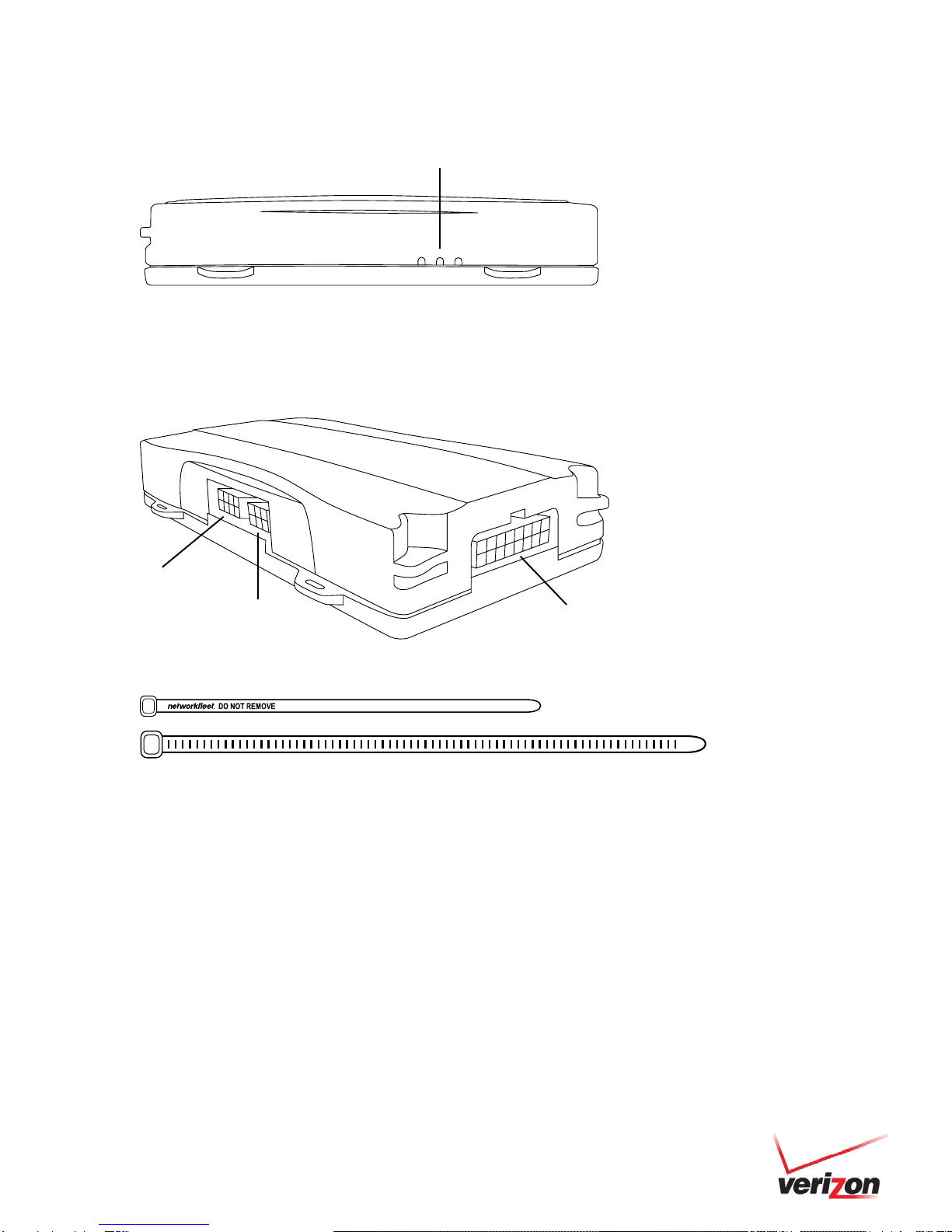
Note: All 5500 and 5200 units are shipped with a knock-out panel covering the sensor/serial ports. In order to access those
ports, you must use an X-ACTO knife to slice off 2 of the 3 tabs in order to remove the knock-out panel.
Before installing a unit, verify that the vehicle’s battery voltage is at least 12.5 V. If the voltage is lower than 12.5 V, the
battery’s health may need to be verified by a professional to determine if the battery needs to be replaced. While the 5000
series units go into a low power mode, the units still draw an average of 16 mA. Also, having two or more devices plugged
into the OBD-II port and/or the auxiliary port results in additional current draw from the battery.
Prior to installing the Networkfleet device, please start the vehicle and note any indicator lights showing on the vehicle
console which show any vehicle issues, should they be present.
LED Indicator Lights
Side of Unit
Data Port
Sensor Port
Serial Port
Zip Ties (x4)

5
Harness Options for the 5000 Product Line
Prior to installation, you must select and order the appropriate harness for your vehicle type. The Light/Medium Duty OBD-
II Harness and the Heavy Duty Harnesses are compatible with both the 5500 and 5200 hardware devices. Please refer to
the list below to verify harness compatibility for each of the 5000 series devices:
5500 (Diagnostic Capable Hardware)
•Light/Medium Duty OBD-II Harness
•Heavy Duty Harnesses (6-pin, 9-pin, or 9-pin “D”)
•Quick Install Harness
5200 (Non-Diagnostic Hardware)
•Universal Harness
•Light/Medium Duty OBD-II Harness
•Heavy Duty Harnesses (6-pin, 9-pin, or 9-pin “D”)
•Quick Install Harness
OBD-II Replacement
Connector
Light/Medium Duty OBD-II Harness
Universal Harness (5200 Only)
Bypass
Connector
Core Connector for the
Light/Medium Duty
OBD-II Harness (X1)
Harness Adapters for the Light/Medium
Duty OBD-II Harness (X8)
Harness
Connector
Embedded Solutions
Quick Install Harness
OBD-II Replacement
Connector
Harness
Connector

6
Heavy Duty Harnesses
There are 3 different harness options for Heavy Duty vehicle installations:
6-pin Harness, 9-pin Harness, and 9-pin “D” Harness.
6-pin Harness
9-pin “D” Harness
9-pin Harness

7
Light/Medium Duty OBD-II Harness Installation
Select an Adapter that most resembles the shape of the OBD-II port of the vehicle.
Use these guidelines to match an adapter to the vehicle it is most likely to fit (each adapter is stamped with a number).
Ford, GM (1), (6), or (8)
Honda, Lexus, Toyota, Chrysler (2)
Toyota*, Chrysler* (2a)
GM, Saturn (3) | Mercedes, BMW (4)
Porsche, Audi, Volkswagen (5)
Volvo (6) | Saab (7)
Note:
For certain Toyota and Chrysler vehicles, you may need to adjust
the #2 adapter by removing the clips on the top and bottom of the
adapter. To the right is an example of the adjusted adapter labeled
(2a).

8
Light/Medium Duty OBD-II Harness Installation
Core Connector Assembly
1. Snap the selected plastic adapter to the back of the Core Connector.
2. Attach the Core Connector to the OBD-II Replacement Connector.
Data Port Connection
Connect the Harness Connector to the Data Port.
OBD-II
Replacement
Connector
Adapter
Bypass
Connector
Harness
Connector
Networkfleet
Unit
Core
Connector
Data Port

9
Light/Medium Duty OBD-II Harness Installation
Connecting to the OBD-II Port
1. With the vehicle’s engine OFF, remove the vehicle’s OBD-II
port. The OBD-II Connector may be hidden behind a hush
panel.
a. To remove the connector, you may need to
remove screws or depress the clips.
2. Connect the Bypass Connector to the vehicle’s OBD-II port
that was previously removed.
3. Attach the Core Connector to the position where the original
OBD-II connector was installed. Secure it with the screws or
clips removed from the OBD-II Connector’s original position
(if applicable).
•5500 Series units installed with a light duty harness cannot be installed along with lift gates that are plugged into
the OBD port. Refer to the TIB: Lift Gates and Unit Interference.
•If other devices besides the 5500 series unit need to be plugged into the OBD port, please refer to the TIB: Scan
Tool Detection and Aftermarket Devices.
Networkfleet Unit
Core Connector
Bypass Connector
Original OBD-II Port
To Vehicle

10
Heavy Duty Harness Installation
Connecting to the Diagnostic Link Connector (DLC) Port
1. With the vehicle’s engine OFF, unscrew the DLC port from its position under
the dashboard*. In most cases, the DLC port is located under the dashboard
on the left side of the steering wheel, facing toward the floorboard.
2. Plug the Bypass Connector of the harness into the DLC port that was
previously removed from the vehicle in step 1. For the 9-pin connector, turn
the rotating cap clockwise to lock into place.
3. Mount the Core Connector of the harness into the place in which the DLC
port originally resided.
*Note: DLC Port Connector may also be located near or
behind the driver seat.
Dashboard
Networkfleet Unit
Core Connector
Bypass Connector
Original DLC Port
To Vehicle
Ce manuel convient aux modèles suivants
1
Table des matières
Autres manuels Verizon GPS

Verizon
Verizon Asset Guard BX Manuel utilisateur

Verizon
Verizon ThingSpace Guide d'application

Verizon
Verizon AI-110 Feuille d'instructions

Verizon
Verizon Visirun B1N Manuel utilisateur

Verizon
Verizon AI-111 Feuille d'instructions

Verizon
Verizon Networkfleet Asset Guard PW Manuel utilisateur

Verizon
Verizon orbic SPEED Manuel utilisateur


