Vents RS-PS Series Manuel utilisateur

RS-...-PS
Thyristor speed controller
USER'S MANUAL

EN
2
This user’s manual is a main operating document intended for technical, maintenance,
and operating staff.
The manual contains information about purpose, technical details, operating
principle, design, and installation of the RS-...-PS unit and all its modifications.
Technical and maintenance staff must have theoretical and practical training in the
field of ventilation systems and should be able to work in accordance with workplace
safety rules as well as construction norms and standards applicable in the territory of
the country.
Safety requirements 3
Brief description 5
Delivery set 5
Design and operating principle 8
Mounting and set-up 8
Connection to power mains 10
Technical maintenance 11
Troubleshooting 12
Storage and transportation regulations 13
Manufacturer’s warranty 14
CONTENTS
FOLLOW THE USER’S MANUAL REQUIREMENTS TO ENSURE
DURABLE AND
TROUBLE-FREE OPERATION OF THE UNIT

EN
3
SAFETY REQUIREMENTS
All user’s manual requirements as well as the provisions of all the applicable local
and national construction, electrical, and technical norms and standards must be
observed when installing and operating the unit.
Disconnect the unit from the power supply prior to any connection, servicing,
maintenance, and repair operations.
Only qualied electricians with a work permit for electrical units up to 1000 V
are allowed for installation. The present user’s manual should be carefully read
before beginning works.
Check the unit for any visible damage of the impeller, the casing, and the grille before
starting installation. The casing internals must be free of any foreign objects that can
damage the impeller blades.
While mounting the unit, avoid compression of the casing! Deformation of the casing
may result in motor jam and excessive noise.
Misuse of the unit and any unauthorised modifications are not allowed.
Do not expose the unit to adverse atmospheric agents (rain, sun, etc.).
Transported air must not contain any dust or other solid impurities, sticky substances,
or fibrous materials.
Do not use the unit in a hazardous or explosive environment containing spirits,
gasoline, insecticides, etc.
Do not close or block the intake or extract vents in order to ensure the efficient air
flow.
Do not sit on the unit and do not put objects on it.
The information in this user’s manual was correct at the time of the document’s
preparation.
The Company reserves the right to modify the technical characteristics, design,
or configuration of its products at any time in order to incorporate the latest
technological developments.
Never touch the unit with wet or damp hands.
Never touch the unit when barefoot.

EN
4
This unit is not intended for use by persons (including children) with reduced
physical, sensory or mental capabilities, or lack of experience and knowledge, unless
they have been given supervision or instruction concerning use of the unit by a
person responsible for their safety.
Children should be supervised to ensure that they do not play with the unit.
Connection to the mains must be made through a disconnecting device, which
is integrated into the fixed wiring system in accordance with the wiring rules for
design of electrical units, and has a contact separation in all poles that allows for full
disconnection under overvoltage category III conditions.
THE PRODUCT MUST BE DISPOSED SEPARATELY AT THE END
OF ITS SERVICE LIFE.
DO NOT DISPOSE THE UNIT AS UNSORTED DOMESTIC WASTE.

EN
5
BRIEF DESCRIPTION
The unit provides manual speed control of voltage-controlled motors (230 V/50 Hz)
by varying the voltage supplied by adjusting the phase angle.
Suitable for wall (IP44) and built-in (IP54) mounting.
The splash-proof casing allows the unit to be used in harsh working environments.
The orange LED indicates the operating status.
The controller allows the control of several motors, as long as the total current
consumption does not exceed the current limit of the controller.
All models have an optional (non-adjustable) 230 V output.
Technical data
• Smooth speed control.
• Adjustment from minimum to maximum speed.
• Adjustment of the minimum speed with the integrated trimmer.
• Fuse 5 x 20 mm, spare fuse included.
• Operating status indication.
Speed controller – 1 pc.
Fuse holder with a spare fuse – 1 pc.
User’s manual – 1 pc.
Packing – 1 pc.
DELIVERY SET

EN
6
Name RS-0.5-PS RS-1.5-PS RS-2.5-PS RS-4.0-PS
Voltage [V/Hz] 230/50
Fan motor operating
voltage [V/Hz] 230/50
Min. load current [A] 0.1 0.15 0.25 0..4
Max. load current [A] 0.5 1.5 2.5 4.0
Rated current of the fuse
[A] 0.63 1.5 2.5 4.0
Wire cross section [mm2] max. 2.5
Maximum ambient air
temperature [°C] +35
Weight [kg] 0,23 0,24 0,29 0,36
SEC class IP44 (flush mounting)
IP54 (surface mounting)
BEFORE MOUNTING MAKE SURE THE CASING DOES NOT
CONTAIN ANY FOREIGN OBJECTS (E.G. FOIL, PAPER).
EN
7
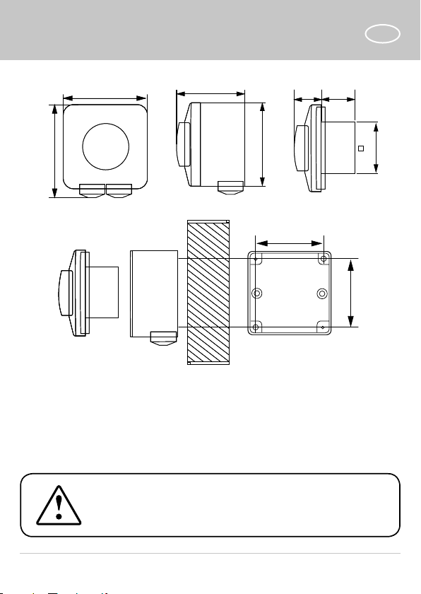
89 82
62
62
7
50
82 65 24 32
WHILE INSTALLING THE UNIT ENSURE CONVENIENT ACCESS
FOR SUBSEQUENT MAINTENANCE AND REPAIR.

EN
8
MOUNTING AND SET-UP
min
N N
Fuse
Minimum speed
adjustment trimmer
Operating status
indicator
DESIGN AND OPERATING PRINCIPLE
89 82
62
62
7
50
82 65 24 32
The controller should be installed on a vertical wall indoors in a hidden mounting box.
Inspect the unit visually and check the casing for integrity.

EN
9
Flush mounting (IP44)
To connect the controller to power mains, follow the steps below:
• Cut off power supply.
• Remove the control knob of the controller.
• Detach the fasteners and remove the decorative cover.
• Disconnect the controller fasteners from the mounting box and remove the
controller.
• Lead the connecting wires into the mounting box.
• Connect the controller as shown in the wiring diagram.
• The conductors are connected to the unit using screw terminals.
• Install the controller in the mounting box with the terminal block at the bottom.
• Install the mounting box in the wall with the connection terminals facing
downwards.
• Apply the mains voltage and switch on the controller.
• Adjust the minimum fan speed at the end position of the control knob.
• Turn of the controller.
• Wait for the fan to stop.
• Turn on the controller to the minimum speed, the fan should rotate steadily at the
minimum speed.
• Put on the decorative cover.
• Put on the control knob.
• Unscrew the knob to the off position.
• The system is ready for operation.
Surface mounting (IP54)
To connect the controller to power mains, follow the steps below:
• Cut off power supply.
• Fasten the casing to the wall, including cable routing.
• Remove the control knob of the controller.
• Detach the fasteners and remove the decorative cover.
• Lead the connecting wires into the mounting box.
• Connect the controller as shown in the wiring diagram.
• The conductors are connected to the unit using screw terminals.

EN
10
Power supply 230 V/50 Hz
Non-regulated 230 V/2 A output
N Neutral
Regulated motor output
CONNECTION TO POWER MAINS
• Install the inner part of the controller into the mounting box with the screws.
• Apply the mains voltage and switch on the controller.
• Adjust the minimum fan speed at the end position of the control knob.
• Turn of the controller.
• Wait for the fan to stop.
• Turn on the controller to the minimum speed, the fan should rotate steadily at the
minimum speed.
• Install the decorative cover.
• Put on the control knob.
• Unscrew the knob to the off position.
• If necessary, drill a 5 mm hole for condensation water outlet at the base in case of
wall mounting.
• The system is ready for operation.
Ce manuel convient aux modèles suivants
4
Table des matières
Autres manuels Vents Contrôleurs


