
Varec 6700 Manuel utilisateur

IOM002GVAE1818
Automation Solutions for oil & gas, defense and aviation applications
Installation and Operations Manual
Dispatch and
6700 Liquid Level Indicator
Accurate gaugeboard indicator for level
measurement


Varec, Inc. iii
Copyright
2018, All rights reserved. Printed in the United States of America.
Except as permitted under the United States Copyright Act of 1976, no part of this publication
may be reproduced, stored in a retrieval system or transmitted in any form or by any means -
electronic, mechanical, photocopying, recording, or otherwise - without the prior written
permission of the Publisher:
Varec, Inc.
5834 Peachtree Corners East
Peachtree Corners (Atlanta), Georgia 30092
Phone: (770) 447-9202
Fax: (770) 662-8939
Trademarks Acknowledged
Varec, Inc. recognizes all other trademarks. Trademarks of other products mentioned in this
manual are held by the companies producing them.
FuelsManager®, TankView®, TacFuels®, Varec®, 8130 RTU8130®, and FuelsManager
IntoPlane® are registered trademarks of Varec, Inc.
HART® is a registered trademark of HART Communication Foundation, Austin, USA
ToF® is a registered trademark of the company Endress+Hauser GmbH+Co. KG, Maulburg,
Germany
FieldCare® is a registered trademark of the company Endress+Hauser Flowtec AG,
Rheinach, CH
All other product and service names mentioned are the trademarks of their respective
companies.

Disclaimer of Warranties
The contract between the Seller and the Buyer states the entire obligation of the Seller. The
contents of this instruction manual shall not become part of or modify any prior or existing
agreement, commitment, or relationship between the Seller and Buyer. There are no express or
implied warranties set out in this instruction manual. The only warranties that apply are those
in the existing contract between the Seller and Buyer.
The 6700 Liquid Level Indicator (LLI) has not been tested by Varec under all possible operational
conditions, and Varec may not have all the data relative to your application. The information in
this instruction manual is not all inclusive and does not and cannot take into account all unique
situations. Consequently, the user should review this product literature in view of his or her
application. If you have any further questions, please contact Varec for assistance.
Limitations of Seller's Liability
In the event that a court holds that this instruction manual created some new warranties, Seller's
liability shall be limited to repair or replacement under the standard warranty clause. In no case
shall the Seller's liability exceed that stated as Limitations of Remedy in the contract between
the Seller and Buyer.
Use of parts that are not manufactured or supplied by Varec voids any warranty and relieves
Varec of any obligation to service the product under warranty. Varec recommends the use of
only Varec manufactured or supplied parts to maintain or service Varec 6700 Liquid Level
Indicator.
Terms of Use
The information provided in this document is provided "as is" without warranty of any kind.
Varec, Inc. disclaim all warranties, either express or implied, including the warranties of
merchantability and fitness for a particular purpose. In no event shall Varec, Inc. or its suppliers
be liable for any damages whatsoever including direct, indirect, incidental, consequential, loss
of business profits or special damages, even if Varec, Inc. or its suppliers have been advised of
the possibility of such damages.
This manual is solely intended to describe product installation and functions and should not be
used for any other purpose. It is subject to change without prior notice. This manual was
prepared with the highest degree of care. However, should you find any errors or have any
questions, contact one of our service offices or your local sales agent.
iv Installation and Operations Manual

Safety Precaution Definitions
Caution! Damage to equipment may result if this precaution is disregarded.
Warning! Direct injury to personnel or damage to equipment which can cause injury to
personnel may result if this precaution is not followed.
Safety Precautions
Read this manual carefully and make sure you understand its contents before using this product.
Follow all instructions and safety guidelines presented in this manual when using this product.
If the user does not follow these instructions properly, Varec cannot guarantee the safety of the
system.
Note Comply with all applicable regulations, codes, and standards. For safety precautions,
the user should refer to the appropriate industry or military standards.
Caution! Electrical Hazard! Read and understand static and lightning electrical protection
and grounding described in API 2003. Make certain that the tank installation, operation,
and maintenance conforms with the practice set forth therein.
Warning! Make certain that the tank is empty and not in service. Ensure that the tank has
been leak and pressure tested as appropriate for the liquid to be stored. Observe
appropriate safety precautions in flammable or hazardous liquid storage areas. Do not
enter a tank that has contained hydrocarbons, vapors, or toxic materials until a gas free
environment is certified. Carry breathing equipment when entering a tank where oxygen
may be displaced by carbon dioxide, nitrogen, or other gases. Wear safety glasses as
appropriate. Use a hard hat.
Warning! Under most circumstances, the mechanical connections between the guide
cables and the anchors provide a resistance to ground that is adequate for the safe electrical
drain of electrostatic charges that may accumulate in the tank and the product. Additional
grounding may be needed for products with low flash points. Worker activity and worker
clothing may accumulate electrostatic charges on the body of a worker. Care should be
used in flammable environments to avoid the hazard. Observe American Petroleum Institute
(API) Recommended Practice 2003 or other appropriate industry or military standard.
Varec, Inc. v

vi Installation and Operations Manual
ATEX Exemption
The 6700 Liquid Level Indicator (LLI) is considered a simple apparatus. It moves very slowly, and
has a low capacity to store energy. It is incapable of forming hot surfaces or other ignition
sources, even in cases of rare malfunction. Simple apparatus are not to be classified as ATEX
equipment or to be marked according to ATEX Directive 2014/34/EU.
For use in gas groups IIA, IIB, and IIC.
Installation Location Wetted Parts
(float, cable, bottom anchor,
top anchors, sheave elbows)
Non-Wetted Parts
(gaugeboard, level indicator)
Hazardous locations – Zone 0 Yes No
Hazardous locations – Zone 1 Yes Yes
Hazardous locations – Zone 2 Yes Yes
Normal (nonhazardous) locations Yes Yes

Varec, Inc. vii
Contents
1 Introduction . . . . . . . . . . . . . . . . . . . . . . . . . . . . . . . . . . . . . . . . . . . . . . . . 1
Getting Started . . . . . . . . . . . . . . . . . . . . . . . . . . . . . . . . . . . . . . . . . . . . . . . . . . . . . . . . . . . . .1
Accessories . . . . . . . . . . . . . . . . . . . . . . . . . . . . . . . . . . . . . . . . . . . . . . . . . . . . . . . . . . . . . . .2
Float Ground Kit . . . . . . . . . . . . . . . . . . . . . . . . . . . . . . . . . . . . . . . . . . . . . . . . . . . . . .8
2 Installation . . . . . . . . . . . . . . . . . . . . . . . . . . . . . . . . . . . . . . . . . . . . . . . . . 9
Oil Seal Installations . . . . . . . . . . . . . . . . . . . . . . . . . . . . . . . . . . . . . . . . . . . . . . . . . . . . . . . .11
Installation of Oil Seal, 8.5-Inch Water Column Operating Pressure Model . . . . . . . . 12
Installation of Oil Seal, 27-Inch Water Column Operating Pressure . . . . . . . . . . . . . .13
Cone Roof Tank Installation . . . . . . . . . . . . . . . . . . . . . . . . . . . . . . . . . . . . . . . . . . . . . . . . . .13
Connecting the Tape to the Float . . . . . . . . . . . . . . . . . . . . . . . . . . . . . . . . . . . . . . . .21
Initial Calibration . . . . . . . . . . . . . . . . . . . . . . . . . . . . . . . . . . . . . . . . . . . . . . . . . . . . .22
Initial Lubrication . . . . . . . . . . . . . . . . . . . . . . . . . . . . . . . . . . . . . . . . . . . . . . . . . . . . . 23
Reassembly . . . . . . . . . . . . . . . . . . . . . . . . . . . . . . . . . . . . . . . . . . . . . . . . . . . . . . . .24
Cone Roof Tank (Bolted Installation) . . . . . . . . . . . . . . . . . . . . . . . . . . . . . . . . . . . . . . . . . . .24
Connecting the Tape to the Float . . . . . . . . . . . . . . . . . . . . . . . . . . . . . . . . . . . . . . . .27
Initial Calibration . . . . . . . . . . . . . . . . . . . . . . . . . . . . . . . . . . . . . . . . . . . . . . . . . . . . .28
Initial Lubrication . . . . . . . . . . . . . . . . . . . . . . . . . . . . . . . . . . . . . . . . . . . . . . . . . . . . . 29
Reassembly . . . . . . . . . . . . . . . . . . . . . . . . . . . . . . . . . . . . . . . . . . . . . . . . . . . . . . . .30
Cone Roof Tank Installation (Fiberglass Tank) . . . . . . . . . . . . . . . . . . . . . . . . . . . . . . . . . . .32
Connecting the Tape to the Float . . . . . . . . . . . . . . . . . . . . . . . . . . . . . . . . . . . . . . . .34
Initial Calibration . . . . . . . . . . . . . . . . . . . . . . . . . . . . . . . . . . . . . . . . . . . . . . . . . . . . .35
Initial Lubrication . . . . . . . . . . . . . . . . . . . . . . . . . . . . . . . . . . . . . . . . . . . . . . . . . . . . . 36
Reassembly . . . . . . . . . . . . . . . . . . . . . . . . . . . . . . . . . . . . . . . . . . . . . . . . . . . . . . . .37
In-service Tank Installations . . . . . . . . . . . . . . . . . . . . . . . . . . . . . . . . . . . . . . . . . . . . . . . . . .39
General Preparation . . . . . . . . . . . . . . . . . . . . . . . . . . . . . . . . . . . . . . . . . . . . . . . . . .40
Independent Pipe Support Structure . . . . . . . . . . . . . . . . . . . . . . . . . . . . . . . . . . . . . . . . . . .40
Installation of Model 228 Inspection Hatch to Existing Manhole Cover . . . . . . . . . . . . . . . . . 41
Anchor Bar Installation . . . . . . . . . . . . . . . . . . . . . . . . . . . . . . . . . . . . . . . . . . . . . . . . . . . . . . 41
Float Installation . . . . . . . . . . . . . . . . . . . . . . . . . . . . . . . . . . . . . . . . . . . . . . . . . . . . . . . . . . .44
Initial Lubrication . . . . . . . . . . . . . . . . . . . . . . . . . . . . . . . . . . . . . . . . . . . . . . . . . . . . . 46
Reassembly . . . . . . . . . . . . . . . . . . . . . . . . . . . . . . . . . . . . . . . . . . . . . . . . . . . . . . . .47
Installation of Model 226 for 20 and 24 Inch Manhole Covers with API Drilling . . . . . . . . . . .47
Typical Auxiliary Equipment Installation . . . . . . . . . . . . . . . . . . . . . . . . . . . . . . . . . . . . . . . . .47
3 Operation . . . . . . . . . . . . . . . . . . . . . . . . . . . . . . . . . . . . . . . . . . . . . . . . . 49
Initial Operation . . . . . . . . . . . . . . . . . . . . . . . . . . . . . . . . . . . . . . . . . . . . . . . . . . . . . . . . . . .49
Normal Operation . . . . . . . . . . . . . . . . . . . . . . . . . . . . . . . . . . . . . . . . . . . . . . . . . . . . . . . . . .49
Calibration and Volume Measurement . . . . . . . . . . . . . . . . . . . . . . . . . . . . . . . . . . . . . . . . . . 49
4 Maintenance . . . . . . . . . . . . . . . . . . . . . . . . . . . . . . . . . . . . . . . . . . . . . . . 51
Periodic Maintenance . . . . . . . . . . . . . . . . . . . . . . . . . . . . . . . . . . . . . . . . . . . . . . . . . . . . . . .51
Electrostatic Discharge Hazard . . . . . . . . . . . . . . . . . . . . . . . . . . . . . . . . . . . . . . . . . . . . . . .51
Lubrication . . . . . . . . . . . . . . . . . . . . . . . . . . . . . . . . . . . . . . . . . . . . . . . . . . . . . . . . . . . . . . .51
Oil Recommendations for Oil Seal Accessory Units . . . . . . . . . . . . . . . . . . . . . . . . . .52

viii Installation and Operations Manual
Inspection . . . . . . . . . . . . . . . . . . . . . . . . . . . . . . . . . . . . . . . . . . . . . . . . . . . . . . . . . . . . . . . . 52
Troubleshooting Common Problems . . . . . . . . . . . . . . . . . . . . . . . . . . . . . . . . . . . . . . . . . . .52
5 Specifications . . . . . . . . . . . . . . . . . . . . . . . . . . . . . . . . . . . . . . . . . . . . . . 55
Liquid Level Indicator . . . . . . . . . . . . . . . . . . . . . . . . . . . . . . . . . . . . . . . . . . . . . . . . . . . . . . .55
Standard Installation Kits . . . . . . . . . . . . . . . . . . . . . . . . . . . . . . . . . . . . . . . . . . . . . . . . . . . .55
Standard Float Specifications . . . . . . . . . . . . . . . . . . . . . . . . . . . . . . . . . . . . . . . . . . . . . . . . .55
Bottom Anchor Bar Weight . . . . . . . . . . . . . . . . . . . . . . . . . . . . . . . . . . . . . . . . . . . . . . . . . . .56
Other Specifications . . . . . . . . . . . . . . . . . . . . . . . . . . . . . . . . . . . . . . . . . . . . . . . . . . . . . . . .56
Reference Part Numbers . . . . . . . . . . . . . . . . . . . . . . . . . . . . . . . . . . . . . . . . . . . . . . . . . . . .56
Indicator Part Numbers . . . . . . . . . . . . . . . . . . . . . . . . . . . . . . . . . . . . . . . . . . . . . . . .57
Float Part Numbers . . . . . . . . . . . . . . . . . . . . . . . . . . . . . . . . . . . . . . . . . . . . . . . . . . .58
Sheave Elbow Part Numbers . . . . . . . . . . . . . . . . . . . . . . . . . . . . . . . . . . . . . . . . . . .59
Bottom Anchor Bar Weight Part Number . . . . . . . . . . . . . . . . . . . . . . . . . . . . . . . . . .60
Oil Seal Accessory Part Numbers . . . . . . . . . . . . . . . . . . . . . . . . . . . . . . . . . . . . . . . .61
6 Order Codes . . . . . . . . . . . . . . . . . . . . . . . . . . . . . . . . . . . . . . . . . . . . . . . 63
Order Code Table . . . . . . . . . . . . . . . . . . . . . . . . . . . . . . . . . . . . . . . . . . . . . . . . . . . . . . . . . .63
Varec, Inc. 1
Chapter 1
Introduction
This manual is designed to assist the user with the installation, configuration, operation,
maintenance, and troubleshooting of the Varec 6700 Low Pressure Liquid Level Indicator.
Getting Started
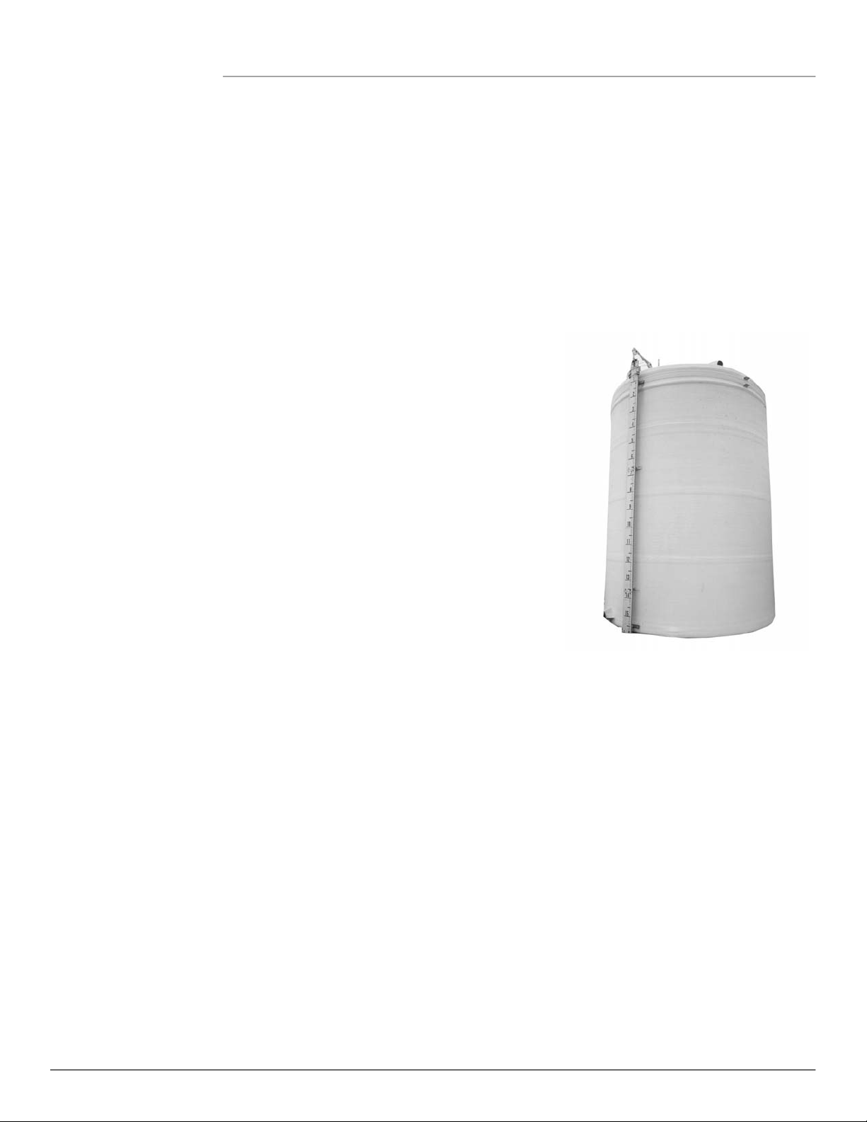
The Varec 6700 Low Pressure Liquid Level Indicators
are for use at atmospheric pressure.
If oil-seal units are installed, pressure of 1.0 psig is
the maximum used with the 27-inch W.C. seal.
A system consists of the gaugeboard, sliding
indicator, float, cables, elbows, and the user
furnished gauge piping which carries the indicator
cable.
Proper operation of the indicator requires the
careful attention of the user to assure high quality
control during installation. Long term, satisfactory
performance of the sight gauge can thus be
obtained. If the installation quality is compromised,
sight gauge accuracy and life may be degraded.
Changes in the liquid level in the tank raise or lower
the float, which moves the indicator cable. Cable
movement drives the indicator up and down the gaugeboard on the side of the tank.
The liquid level in feet and inches, or meters, decimeters, and two-centimeter increments is
indicated by the indicator position on the gaugeboard. The user may then convert the liquid
level to units of volume. This may be accomplished manually, or Varec's computer aided data
acquisition system may perform the task.
When the indicator is at the top of the gaugeboard, the tank is empty with the float at the
bottom of the tank.
Chapter 2, Installation, covers installations to be performed on tanks that are empty and are
not in service. The section, In Service Tank Installations, covers the additional procedures that
are required for making installations on tanks that are in service.
Varec service contracts provide the user substantial savings for maintaining and refurbishing
the systems. Contact Field Service, a Varec representative or Product Marketing for further
details.

Liquid Level Indicator
2 Installation and Operations Manual
Accessories
Varec manufactures accessories for transmitting and telemetering the information to a Varec
Data Acquisition System. Limit switches may be attached to the Liquid Level Indicator system
to provide signaling functions. Figure 1 through Figure 6 illustrate some of the accessories
available.
Table des matières
Manuels Équipement de réservoir populaires d'autres marques


Flexcon
Flexcon FLU/H2PLU Manuel utilisateur

Harbor Freight Tools
Harbor Freight Tools Centralpneumatic 66839 Instructions de montage

DeVilbiss
DeVilbiss QM T-5 Series Manuel de référence

Regulus
Regulus PS 80 Z Manuel utilisateur

KIESELMANN
KIESELMANN TDAM 6180 Manuel utilisateur

Worthington
Worthington Amtrol THERM-X-TROL ST-447C Instructions d'installation