ValveSentry VS100 Manuel utilisateur

1
CustomControls,LLC
ValveSentry™
USER’S MANUAL
VS100
IMPORTANT! PLEASE READ CAREFULLY AND SAVE
This user’s manual contains important information about your ValveSentry™ device’s operation. If you are installing this ValveSentry™ device
for use by others, you must leave this manual—or a copy of it—with the end user. 170328

2
CustomControls,LLC

3
CustomControls,LLC
TABLE OF CONTENTS
Page No.
Introduction . . . . . . . . . . . . . . . . . . . . . . . . . . . . . . . . . . . . . . . . . . . . . . . . . . . 3
Basic Safety Information . . . . . . . . . . . . . . . . . . . . . . . . . . . . . . . . . . . 4
What’s in the Box? . . . . . . . . . . . . . . . . . . . . . . . . . . . . . . . . . . . . . . . 5
Installation Instructions . . . . . . . . . . . . . . . . . . . . . . . . . . . . . . . . . . . . . . . . . . 6
Installation on a Gate Valve . . . . . . . . . . . . . . . . . . . . . . . . . . . . . . . . 7
Installation on a Ball Valve . . . . . . . . . . . . . . . . . . . . . . . . . . . . . . . . . 10
Water Sensor Placement . . . . . . . . . . . . . . . . . . . . . . . . . . . . . . . . . 12
Connecting the Controller . . . . . . . . . . . . . . . . . . . . . . . . . . . . . . . . . 13
Battery Installation (IMPORTANT NOTE TO USE 7 AAA BATTERIES) 15
Testing and Maintenance . . . . . . . . . . . . . . . . . . . . . . . . . . . . . . . . . . . . . . . . . 16
Regular Maintenance ………………………………………………………………………………..21
Warranty Information . . . . . . . . . . . . . . . . . . . . . . . . . . . . . . . . . . . . . . . . . . . 21
How to Contact Us …………………………………………………………………………………….23

4
CustomControls,LLC

5
CustomControls,LLC
INTRODUCTION
Thank you for purchasing the ValveSentry™ device. It is an important component of your home security system
protecting against damage from water leaks. This device is suitable to control one valve by turning it on or off
when the sensor detects moisture. This device has a one year limited warranty (see below for details). Please take
a few minutes to thoroughly read this user’s guide, and save for future reference. The more familiar you are with
the information it contains, the easier you will find it to install, operate and maintain your device properly which
ultimately means greater security and peace of mind. If you have any questions about your device, please email

6
CustomControls,LLC
BASIC SAFETY INFORMATION
IMPORTANT!
• The following are important operating instructions and alert you to potentially hazardous situations. Pay special attention to these items.
The ValveSentry device is powerful. It has considerable torque allowing it to open and shut your valve. THEREFORE ALWAYS KEEP YOUR
HANDS AND FINGERS AWAY FROM THE DEVICE while it is powered. If your hand or finger gets caught on a valve or is between the valve and
a pipe, wall or other object while a valve is opening or closing, it could cause injury. That is why you should always unplug and remove the
batteries from the unit prior to installing, adjusting or touching it. Remember that you can always immediately shut down the unit by pressing
the “stop” button on the controller.
•Before you turn off a water source. Be aware of any consequences that can result from your valve being turned off by the ValveSentry device
before installing it. For example, some heating systems can be damaged if water is cut off for any length of time. CustomControls LLC is not
responsible for such damage. Therefore, please deploy the ValveSentry device in a thoughtful manner.
•The ValveSentry device has limitations. This ValveSentry device is not foolproof and is not warranted to protect lives and property from water
damage and associated hazards such as electric shock. The ValveSentry device is not a substitute for insurance. Homeowners and renters
should insure their lives and property. In addition, it is possible, for the ValveSentry device to fail at any time. For this reason you must test
the ValveSentry device monthly, assure it has fresh batteries and is working properly. It is recommended that you replace it with a new
ValveSentry device every 5 years.
•The ValveSentry device is NOT a solution for a “stuck” or frozen valve. The ValveSentry device must be tested on a monthly basis to make
sure that it can turn the valve off. (See testing instructions).
BATTERIES: THE ValveSentry BATTERY HOLDER INCLUDES EITHER A SHORT BAR OR A DUMMY BATTERY. DO
NOT REPLACE THIS WITH A REGULAR BATTERY. DOING SO WILL DESTROY THE VALVESENTRY. THE VALVESENTRY
ONLY REQUIRES 7 AAA BATTERIES. TEST THE ValveSentry DEVICE TO MAKE SURE THAT IT WORKS ON BATTERY
POWER EVERY MONTH.
7
CustomControls,LLC
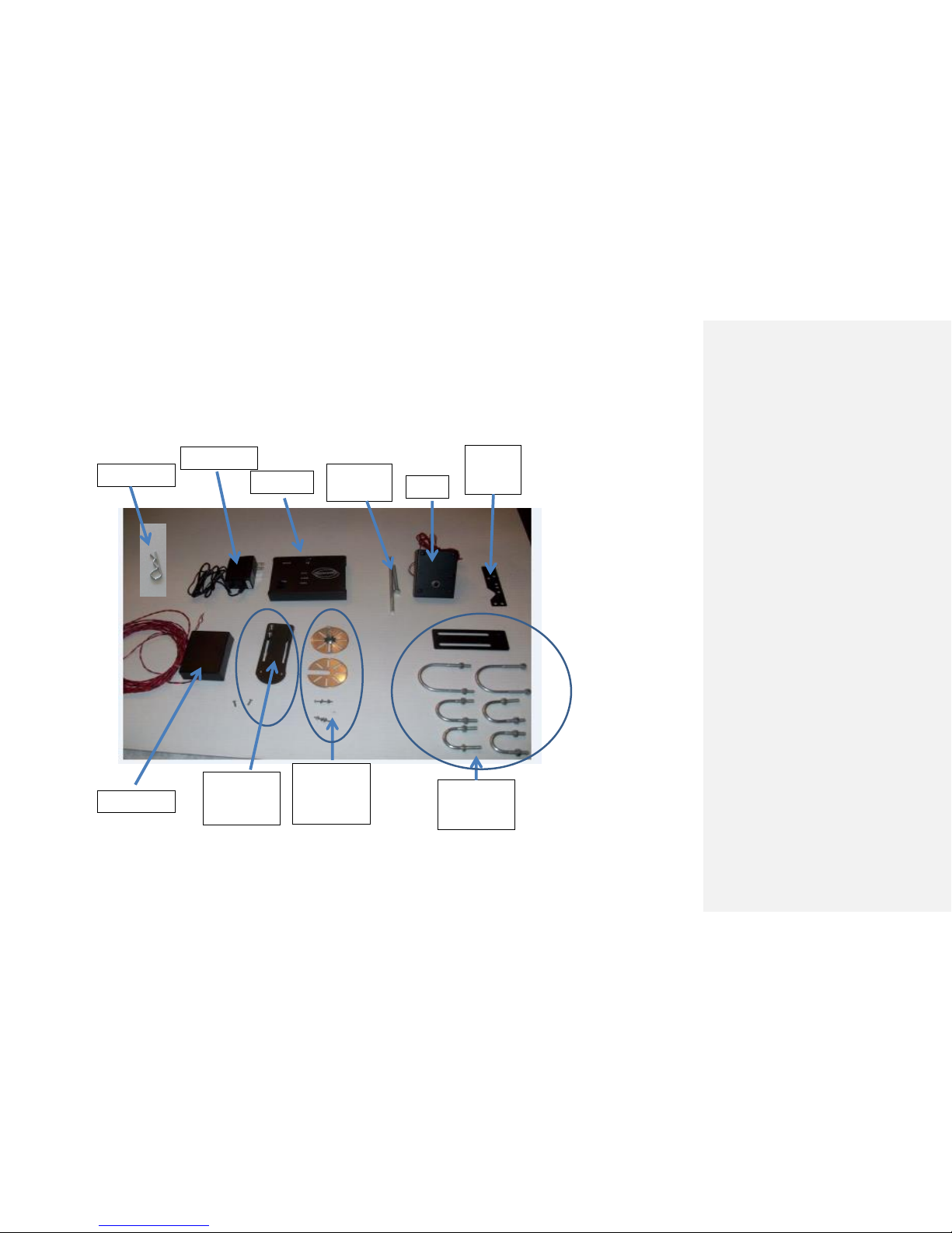
Power Supply
Controller
Connecting
Rods
Motor
Motor
Mount
Bracket
Gate Valve
Handle Mount
(top and bottom discs)
and screws
What’s in the Box?
Water Sensor
Ball Valve
Handle Mount
and screws
Pipe Mount
Bracket and U
Bolts
Cotter Pin

8
CustomControls,LLC
INSTALLATION INSTRUCTIONS
The following installation instructions should allow you to install the ValveSentryt
device. You will need a few screw drivers of various sizes, pliers and a wrench to screw
the ¼ inch bolts on the U Bolts.

9
CustomControls,LLC
How to mount the ValveSentrytm Device to a Gate Valve
Figure A: What it should look when properly installed
Gate Valve
Step 1: Place bottom Gate Valve Handle
Mount disc under gate valve handle.
Step 2: Place Gate Valve Handle
Mount top disc on top of the gate
valve handle centering the shaft
over the center of the handle and
lining up at least two slots to slip #4
screws through.
Step 3: Place 2 or 3 stainless steel
screws through the slots on upper and
lower discs with gate valve handle
sandwiched in between.

10
CustomControls,LLC
Step 4: Twist on and tighten
#4 lock nuts to # 4 screws on
bottom Gate Valve Handle
Mount disc.
Step 5: Place the motor over the top Gate Valve Handle
Mount disc such that motor drive lines up with the shaft on
this disc.
Step 6: Position the Motor Mount Bracket such that it will
be able to line up with the Pipe Mount Bracket after the
Pipe Mount Bracket is installed. Refer to “What it should
look like” picture above (Figure A).
Motor Mount
Bracket
The Motor Mount Bracket contains a number of holes and
is shaped so that it can be mounted to the right side, left
side or front of the motor. It can be mounted on the top
or bottom surface. Choose the position that works best.
Step 7: Screw ¼ inch bolt or
stud (depending upon model)
through top center hole on
Motor Mount Bracket.
Step 8: Hold the Pipe Mount
Bracket and Motor Mount
Bracket in desired positions so
that the bolt or stud will pass
through the hole in Pipe
Mount Bracket.
Pipe Mount
Bracket
Table des matières


